The transmission line theory, in contrary, works in conditions where the transmission line is equal to a part of the signal wavelength. The transmission line is called the distributed parameter circuit.
Field-analysis: Standard circuit analysis, which suggests that physical dimensions of the circuit are much smaller than the electrical wavelength, is the analysis we used to work with. And this circuit is called lumped elements circuit.
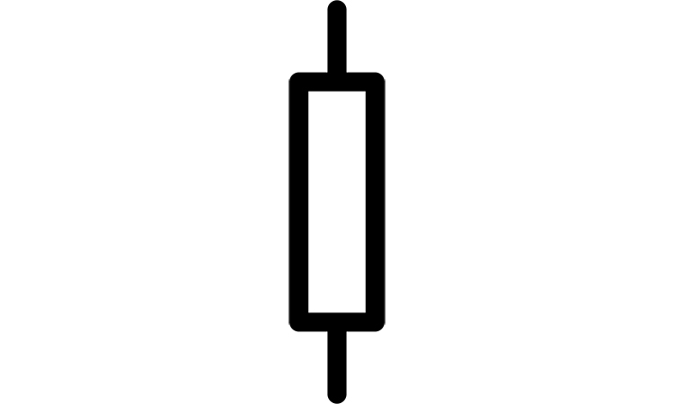
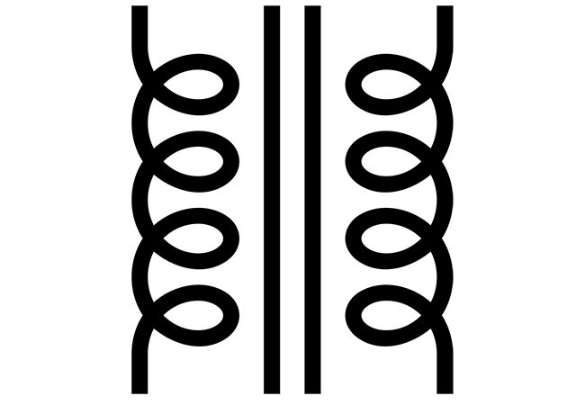
The transmission line always has at least two conductors and is schematically presented with a two-wire line. This two-wired line is characterised with losses and effects due to the proximity of a second conductor. That is why we can represent these effects with resistance, capacitance, conductance and inductance on the scheme (Figure 1).
Combining Kirchhoff’s Laws for voltage and current we can get the telegrapher equations:
For sinusoidal steady-state form:
These equations gives:
and here the propagation constant:The characteristic impedance here is:
the signal wavelength is , and phase velocity is .

Lossless transmission line in transmission line theory.
Let’s consider the lossless transmission line. In this case we can neglect R and G. For this case the propagation constant is: . The characteristic impedance , and the signal wavelength is and phase velocity is .
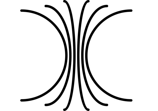
In the discussion above we characterised the transmission line with several parameters R, L, G, C. Let’s now calculate them for the coaxial line. Let’s consider the transmission line with fields E and H. The cross-section of the coaxial transmission line is S, and voltage and current between the conductors is Vejßx and Iejßx.
The magnetic energy is: then .
The electric energy is: then .
The power losses on the conductor are: and
Power dissipation of the dielectric is: and .

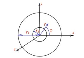
Now, using these formulas the transmission line parameters can be calculated for different geometry of transmission lines. For example, let’s consider coaxial transmission line, like in Figure 2. The travelling TEM fields are: .
The coaxial line is characterised with the propagation constant of material γ, the surface resistivity RS and material filling in the coaxial line is characterised by complex permittivity ɛ, and permeability µ. Using the formula above we have got for transmission line parameters:
Using the same principle for different geometry of transmission lines we can get different transmission parameters.
Let’s consider the power flow in the lossless transmission line. From the theories above the propagation constant for lossless matter: and .
Also from the calculations above we know that impedance for the transmission line is: .
In the case of a coaxial transmission line with the field waveform we considered in the example characteristic, impedance is:
As we saw in the example above for coaxial line, the characteristic of impedance is geometry dependent and will be different for different transmission line forms. The power flow for the coaxial line and mentioned field forms is: .
The power flows travel through the dielectric space between two conductors, and the conductors can not transmit power directly.
Educational content about transmission line theory can also be reached via Reddit community r/ElectronicsEasy.


