As we discussed before, the output voltage for the MOSFET amplifier is non-linear towards the input voltage: =.
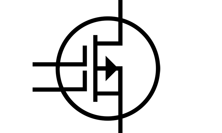
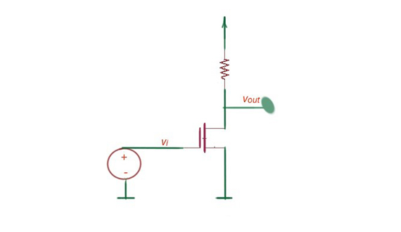
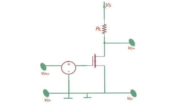
Figure 1 shows the MOSFET amplifier at the small-signal interpretation.
a
b
Figure 1.The MOSFET amplifier and it’s small-signal model.
This non-linearity significantly complicates design development, so linearity of the amplifier is more interesting from the designer point of view. Small-signal approximation states that at small time-varying incremental amplification, the time-changing component will be linear. Figure 2 depicts the transfer characteristics with small-signal interpretation. In this situation the incremental transconductance is , where g is the ratio between input voltage and current. Small-signal gain is .
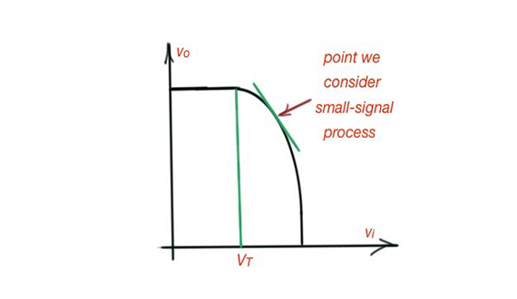
Figure 2. The transfer function for the MOSFET amplifier.
In order to calculate the incremental small-signal response, we have to do a few calculations: we need to find the large-signal response for the certain DC operating point of the signal. And then we must use the Taylor approximation to obtain the small-signal response for this operating point.
Considering the circuit in terms of small-signal approximation we must:
1. Put all components to their operating value.
2. Linearise the behaviour of every circuit component at the operating point.
3. Replace orginal circuit components with their linearised components.
Some handbooks give the extensive explanation of the small-signal approximation of different components of circuits like DC voltage and current sources. In general, we need to find the small-signal approximation of the circuit component so it’small signal deviation for this component is at some specific value for the operation point .
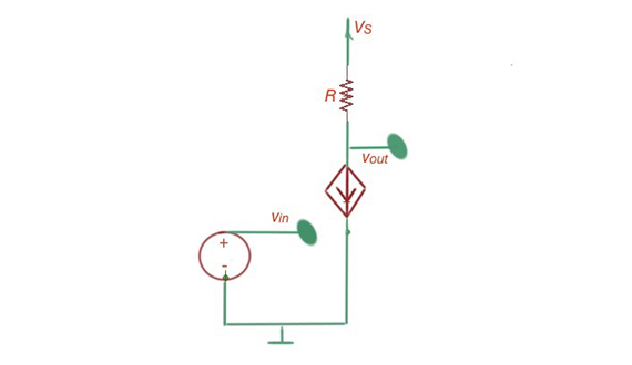
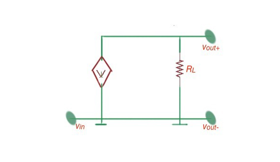
For the MOSFET amplifier, small-signal approximation for the operating current is , and . Figure 3 depicts the amplifier and its small-signal model.
a
b
Figure 3. The difference amplifier and its small signal model.
The input resistance for this model will be , the output resistance is . The current gain for this model will be . Power gain for this scheme will be .
Let’s consider the difference amplifier AD8479 for high quality amplification. This difference amplifier consists of the operational amplifier and resistor network. The output of the difference amplifier , where is the difference-mode gain, and is the common-mode gain. These can lead us to the common mode rejection ratio for the amplifier .[1]
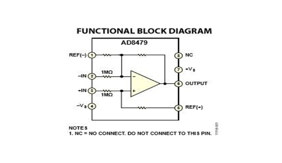
Figure 4. Functional diagram for the difference amplifier AD8479, Analog Devices. [2]
[1] “Foundations of Analog and Digital Electronic Circuits”, Anant Agarwal and J. H. Lang, Elsevier.
[2] AD8479 datasheet, Analog Devices.