The quarter-wave impedance transformer is a device that matches the transmission line and the impedance and is shown in Figure 1. Let’s consider the random transmission line with the characteristic impedance Z0, and the load with resistance R.
The characteristic impedance of the quarter-wave transformer is Z1, the length is . The matching transmission lines are assumed to be lossless. The input impedance here is
. For the . And the characteristic impedance of the arbitrary transmission line is , for the lossless transmission line.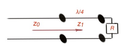
The real quarter-wave impedance transformer experiences a variety of reflected and propagated waves. Let’s consider the case of multiple reflection of the waves. Take a look at Figure 2. There is two transmission lines made with blue dashed circles There is a wave that falls from the side of the Z0.
When it reaches the quarter-wave transformer, part of the wave reflects with the reflection coefficient , another part of the wave propagate with the coefficient T1. The propagated wave passes the length of the quarter-wave transformer reflecting on the load and passing the load partially.
The reflected part of the wave has the reflection coefficient , the propagated wave has the coefficient T2. The reflected part of the wave goes the length of the quarter-wave transformer again and partially reflects on the Z0 with reflection coefficient , partially propagates Z0 with the coefficient T3, and so on. Figure 2 depicts the reflected and propagated waves.
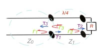
The propagation and reflection coefficients are the following: . As this is an infinite process, the total reflection coefficient is the sum of all the partially reflected waves, which gives the result .
For the steady-state conditions, when the waves travel in the same direction with the same phase velocity, it can be considered as one travelling wave. And all this set of waves travelling in the same direction can be considered as two waves, travelling in opposite directions.
(Microwave Engineering», David M. Pozar, 4th edition).
#5 Transmission line circuit for mismatched load and generator