Let’s consider series and parallel RLC circuits with lumped parameters. They can be used for modelling resonators.
RLC series resonant circuit.
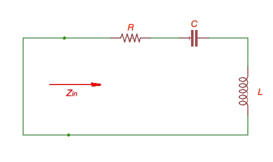
Here . Input resonator power is . Power, loss on the resistor is , power stored at the inductor is . Power stored at capacitor is . Then and .
Resonance happens when , then when .
Resonant circuit can be characterised by quality factor .
Resonator losses can have different nature, including conductor losses, dielectric losses, radiation losses and others. Quality factor of a resonator is called unloaded and assigned as .
.Resonator behaviour near it’s resonance frequency . . Then .
Then . Quality factor can also be a characteristics of a resonator bandwidth .
RLC parallel resonant circuit.
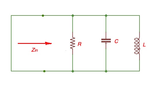
Here . As for the case above we calculate input power for resonator . Resistor power losses are . Energy stored in capacitor , power stored in inductor . As for the first example . And .
When we have a resonance, . Resonant frequency . Resonance in the parallel circuit is called anti-resonance.
Considering circuit frequencies close to resonant, and making similar calculations, . Knowing that , then and bandwidth .
Cases above are for unloaded circuit. Let’s consider the case if the circuit is loaded as outlined below.
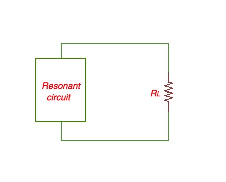
Let’s say the resonance circuit is loaded with the load resistor , then quality factor for external load is .
Then total quality factor is .