This post answers the question how capacitive displacement sensor works. Capacitance of a parallel-plates capacitor is determined by the formula where a is the plate square, d is a distance between plates, and ε is a permittivity of the material between the plates.
The permittivity of the air is .
Doing a simple calculation we can find out that for two parallel plates with 1mm distance and 1m2 the capacitance is .
These type of capacitors are impractical for regular applications, however it is very good as a motion transducer. A motion transducer is a device that can measure displacement of an object. In an motion transducer the capacitor is designed with the variable distance between plates, so one capacitor plate is fixed, and the other is moving, depending on the object position. Capacitance of this capacitor is , is the area of the plates, , is the variable distance between capacitor plates, mm. The sensitivity S of the transducer is the change of the capacitance per change of the displacement: .
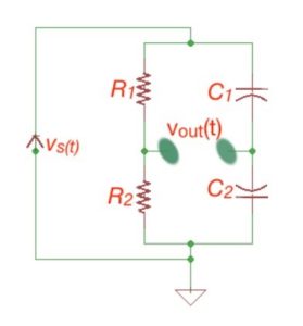
The sensitivity increases for small distance changes. Figure 1 depicts the circuit scheme for capacitance displacement transducers. When the preassure on both sides of the capacitors are equal, then capaitances C1 and C2 are equal. If any pressure changes are detected, then capacitances will change too.
Let’s consider the capacitive displacement transducer as a part of an AC circuit. The idea is that its impedance is the linear function of the displacement under certain conditions. For the AC circuit the capacitance of the capacitor, as we stated above, is:
where a is the capacitor square with some certain constant, so the capacitor impedance is is .
It does mean that certain frequency impedance will change linearly. Let’s consider the capacitance displacement transducer bridge scheme, consisting of two resistors and two variable capacitors, .
This bridge is excited by the AC source. So the output voltage between and is
.
Let’s assume that the nominal capacitance of the the variable capacitor is
where is the area of the plates, and is the distance between the plates. If there is a pressure change across the transducer, then the capacitance of the variable capacitors on the bridge scheme is .
So the impedance of the capacitors will be
so making certain calculations we can obtain the output voltage for the capacitive displacement transducer
So combining the resistances, we see that output voltage will vary as a function of the capacitance displacement.
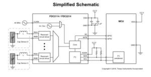
Applications of capacitive displacement sensors are very wide like proximity detection or gesture recognition. Modern capacitive sensing devices include many other components on board, combining additional functions to sensing the displacement. The example is FDC2x1x-Q1, multi-channel family of capacitive sensing solutions by Texas Instruments, which employ the L-C resonator technique. Figure 2 depicts it’s simplified principal scheme. Capacitive sensing is a very low power and low cost solution, and it is also characterised by the high resolution sensing technique.
More educational tutorials can be also accessed via Reddit community r/ElectronicsEasy.