This post answers the question what is filtering in signal processing. The first step towards a proper measurement system is shielded, grounded and wired signals. The next step is conditioning – amplification or filtering. An instrumentation amplifier is the differential amplifier with high input impedance, low bias current and programmable gain.
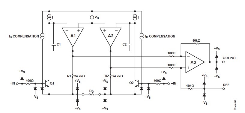
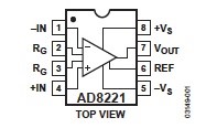
An instrumentational amplifier is usually used to amplify in a noisy environment. Not every amplifier can be used as an instrumentation amplifier. And basically there is a big difference between instrumentation and operational amplifiers. An instrumentation amplifier is a closed-loop gain block. An example of an instrumentation amplifier is shown in Figure 1.
The gain of the instrumentation amplifier is determined by the feedback of the internal resistors, isolated from the amplifier inputs. The input signal goes on both differential inputs. So the instrumental amplifier rejects the common signal on these inputs, keeping only the difference between these two.
That is why the instrumentation amplifier is good for cutting noises and extracting small signals. So, an instrumentation amplifier amplifies the difference between two input signals, rejecting the common parts between them.
The CMR, or common-mode rejection, property of an amplifier is the characteristics of the instrumentation amplifier that cancels the common signal for both inputs and amplifies the different signal. Another characteristic is common mode gain or , which is the ratio of change in the output voltage of the amplifier to the common mode input voltage.
The third important characteristic of an instrumentation amplifier is the differential or common mode gain , which is the ratio of input and output voltages applied differentially to the instrumentation amplifier.
The fourth important instrumentation amplifier characteristic is the common mode rejection ratio or CMRR, which is the ratio of differential gain to the common mode gain. – here is the differential gain of the amplifier, is the common mode voltage of the amplifier input, is the output voltage of the amplifier, when there is a common mode voltage on the input.
The example in the block-diagram of a typical instrumentation amplifier is depicted in Figure 1. Note that all instrumentation amplifiers are equipped with a reference input.
The difference amplifier is a special type of an instrumentation amplifier that consists of the subtractor amplifier, followed by the output buffer. The subtractor part consists of four resistors which are internal of the final amplifier.
The instrumentation amplifier is characterised by the following parameters:
- High AC/DC common-mode rejection
- Low offset voltage and offset voltage drift. The total output offset of the instrumentation amplifier is a complex quantity, combined with several output characteristics, multiplied by the gain
- A matched high input impedance. The high input impedance is important to prevent the loading down of input signal source. The impedances, as was mentioned at the very beginning, should be carefully matched. Typical values of input impedance is 106 – 109 ohm
- Input current errors and low input bias. The bias currents flowing into and out of the instrumentation amplifier creates an offset error. It is prefferable to avoid them
- Low noise. The range of voltages carried by the instrumental amplifier is very wide, and it should be sensitive to the low voltages, operating with very low noise.
- Low non– This parameter is usually specified by the manufacturer, and is measured as a percentage of the full scale. This characteristic is essential for the instrumentation amplifier and can’t be removed by external devices
- Differential to single-ended conversion. This means that the differential signal is amplified, buffered and single-ended output delivered.
- Rail-to-rail output, internal swing. In most applications the instrumentation amplifier is used with rail-to-rail input, so the input or output swing is usually equal to the power supply voltage.
- Combination of power characteristics, slew rate, bandwidth and noise. When the operating current in the instrumentation amplifier is growing, bandwidth is growing, slew rate is rising and noise is lowering. However, high operation current enlarges the power dissipation of the instrumentation amplifier. So in order for the amplifier work correctly, the proper combination of these parameters should be done.
When designing the instrumentational amplifiers with discrete components, we can encounter many problems. However, most of these can be eliminated if the instrumentation amplifier is designed on a monolithic integrated circuit. All modern instrumentation amplifiers are manufactured on a monolithic IC.
Another operation that must be done with signals is filtering, the process of extracting the signal with the required frequency.
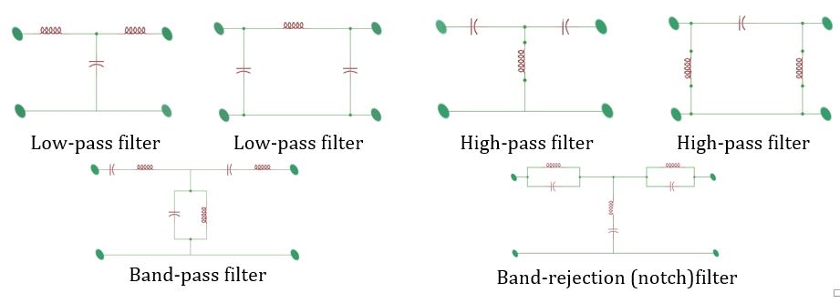
As we will show in the theory of Advanced Circuits Analysis there are four types of filtering – high-pass, low-pass, band-pass, and band-reject and all-pass filter. Filters are characterised with the nominal filter gain, that have some deviation, indicating boundary levels of filter pass gains.
Filters are also characterised with cut-off frequency , the frequency where the pass-band of the filter changes to the stop-band. The frequency , is the frequency that does not allow the gain to grow more that its minimal pass value.
More detail of the different types of filters are described in the Advanced Circuits Analysis module. Filters are also characterised by the order of the characteristics that correspond to the differential equation order. Fast filters are high orders. The schemes of the low-pass, high-pass and band-pass filters are shown in Figure 3.
Filters are also characterised with the parameter , which is quality factor. That represents the sharpness of the filter frequency peak. All these parameters can be found in the datasheet for the chosen filter. A filter is also characterised by the damping rationale, which is proportionally inverse to the quality factor. So the lower the damping ratio the higher the quality factor. Manufacturers that produce both the instrumentation amplifier and filter, for example, are Analog Devices, Maxim Integrated and many others.
More educational tutorials can be accessed via Reddit community r/ElectronicsEasy.
Analogue-to-digital and digital-to-analogue signal conversion