This post gives insight to the topic of transient response using delay. To understand the delay transient response lets apply apply RC model to the first-order system depicted below.
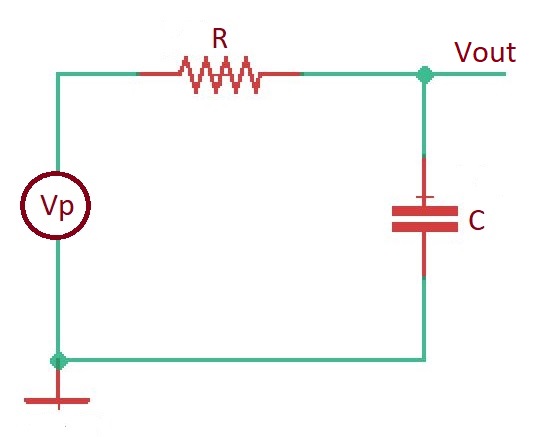
This system has transfer function with step response (depicted below). Here propagation delay will happen when and .
In case of more complex system with several resistances and capacitances the result will look very complex. But it can also be approximated to the simple form like in the case with first-order system.
Most of circuits can be represented in form of RC tree. The tree root is usually a voltage source. Capacitors are at the end of branches as leafs. Here we can introduce a model, that is called Elmore delay model. The Elmore delay model describes the delay between the source and and capacitance at the branches multiplied by correspondent resistance. So .
Read more educational posts at our Reddit community r/ElectronicsEasy.
Source: “CMOS VLSI design a circuits and systems perspective”, Neil H.E. Weste, David Money Harris.