This post covers types of electrical measurement systems. Every engineering task requires the measurement of some physical quantity and converting it to an electrical quantity. The devices that can help in these tasks are sensors and transducers.
Sensors usually convert the change of physical quantity to the change of electrical quantity, and in many cases there are additional manipulations that are needed between the sensor and output. For example, amplification, and these additional manipulations, are called signal conditioning.
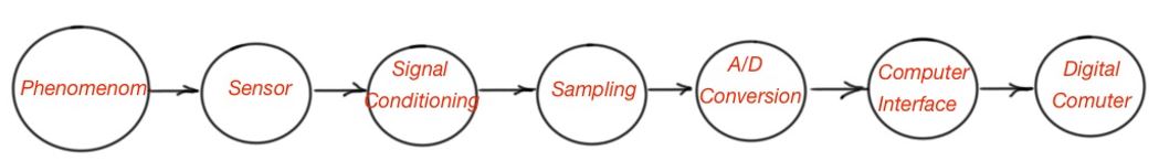
The wiring of the signal conditioning part requires special attention to the grounding and shielding. Very often for the user’s purposes the conditioned sensor signal should be converted to the digital form and displayed on the PC. The set of manipulations to produce the signal that will be displayed in a proper form is called a measurement system. Figure 1 depicts the block diagram of the measurement system.
There are a lot of sensor classifications and there are no universal classifications, because sensors can be classified by the measuring quantity, or by the measuring regime and so on. We will follow one certain classification of sensors based on the measured quantity.
Types of electrical measurement systems: motion and dimensional measurements
These measurements include the detection of absolute and relative position, velocity, acceleration and jerk. There are some sensors that can produce these measurements.
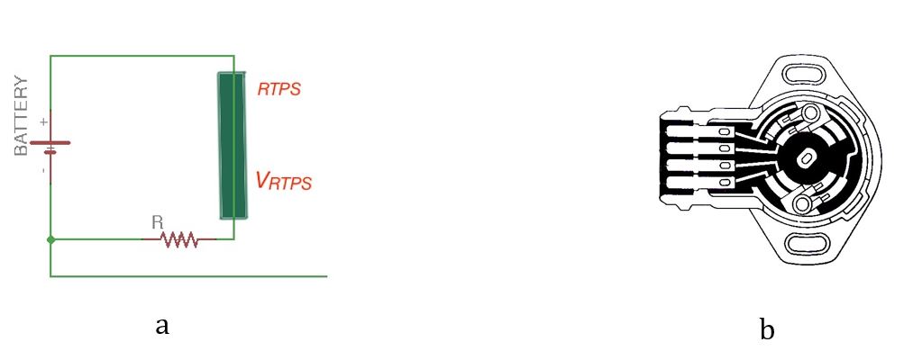
Resistive potentiometer: Resistive Throttle Position Sensor (RTPS) is a sensor that is used to monitor the position of the throttle in automotive vehicles. It is usually placed on the throttle spindle to detect the position directly. Figure 2 depicts the equivalent schemes of the RTPS and its actual picture.
Strain gauges: Resistance strain gauges are devices whose resistance is a function of the strain of the surface of measured object. Strain gauges can also perform measurements of stress, force, torque and pressure. For example, if the measured object is a cylinder, with cross-section A and length L, whose surface is made of conducting material , the resistance is:
If the cylinder is compressed, then the resistance will decrease, and if the cylinder is elongated, the resistance will increase. The Gauge Factor, G, is a relation between the change of length of the measured conductor and the change of it’s resistance:
As the strain is:
, the change of resistance is due to the applied strain .
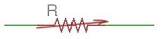
The resistance is zero strain resistance. Figure 3 depicts the resistance strain gauge and its symbol on the equivalent electric circuit.
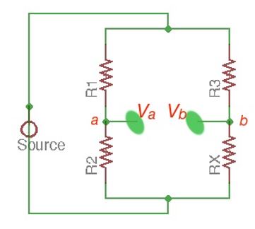
The Wheatstone Bridge is the bridge scheme, and got its name from the designer Charles Wheatstone, designed to measure unknown resistances and calibrate measurement instruments like ampermeters, voltmeters and others. It consists of four resistances connected in parallel, as shown in Figure 4, with the voltage supply and ground zero voltage between two parallel branches.
More educational content can be accessed via Reddit community r/ElectronicsEasy.