Digital circuits implement logic using “if-statements”. The simplest logic operations are .
operation is represented with “*”, operation – with symbol “+”, operation – with operation “”
Example statement: , that means if is true is true, then is true, otherwise is false. Statement is true, when both elements and are true.
Example : , if is true or is true, then is true, otherwise is false. Statement is true, when one of the elements or is true.
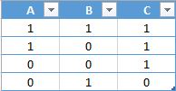
Every logic expression can be described with the truth table. Truth table numerates every possible input value and every possible output value using Boolean functions. Every TRUE correspond to logic “1”, every FALSE correspond to logic “0”. So if we will consider the logical statement , that means is true (“1”), if is true (“1”) is false (“0”), otherwise is false (“0”). Truth table for this statement shows every possibility of this statement in its logical representation, i.e.
Let’s see what happening at the truth table above:
1 line: is true (“1”), is true (“1”), then is true (“1”).
2 line: is true (“1”), is false (“0”), then is true (“1”).
3 line: is false (“0”), is false (“0”), then is true (“1”).
4 line: is false (“0”), is true (“1”), then is false (“0”).
Truth table for the statement , that means is true (“1”), if is false (“0”), else is false (“0”).
1 line: is true (“1”), then is false (“0”).
2 line: is false (“0”), then is true (“1”).
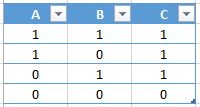
Truth table for . Here if is true (“1”) or is true (“1”), then is true (“1”), else is false (“0”).
1 line: is true (“1”), is true (“1”), then is true (“1”).
2 line: is true (“1”), is false (“0”), then is true (“1”).
3 line: is false (“0”), is true (“1”), then is true (“1”).
4 line: is false (“0”), is false (“0”), then is false (“0”).
Truth table can contain any amount of input values, it will create bigger amount of output values. Bigger amount of input values – bigger amount of output values.


