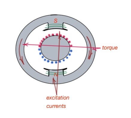
The schematic of a DC machine is depicted below. As you can see it has magnetic poles on both stator and rotor. The torque, created by the DC machine, is the result of magnetic forces between the stator and rotor.
Note that the torque is at maximum when the angle between them is 90 degrees. The field winding wire of the DC machine is usually on the stator, and the armature wire is usually the rotor wire. To keep the torque angle constant, a commutator usually used.
The speed of rotation of electric machine is usually measured in revolutions per minute.
We can differentiate the generator from the motor mathematically. If armature voltage of the electrical machine is less than the back electromotive force, then it is a generator. If the armature voltage of the electrical machine is bigger than the back electromotive force, then the machine is a motor. The equations, that describe the electrical machine are:
Dynamic equations describing DC machines are:
are the equations for armature and field circuit top and bottom.The dynamic torque equation is the following: .
Electric generators
Due to the presence of the magnetic core in the structure of a DC machine, the armature voltage is non-zero when no field current is present. When the field current starts to flow, the back electromotive force is generated in the armature. The most used configuration is when the DC generator contains series shunt and series filed wiring. This generator can be described with the following equations:
.Electric motors
Electric motors are pretty much the same from the point of view of their analysis, but with inverted input and output. The motor can be described with the following equations:
.