Sine-wave signals
In this post we will learn about AC circuits, magnetic circuits and transient processes in these systems, and other aspects of complex circuits.
Single-phase current circuits
Current for single-phase circuits can be described by the formula:
The maximum rating of this current is magnitude , is the period – time of one current oscillation.
Single-phase current frequency is the quantity of oscillations per second , . Single-phase current angular frequency is .
The is called phase and it characterises the state of the oscillating system at a certain moment. Single-phase current is described by the formula: .
This equation is determined by magnitude, frequency and initial phase. Sinusoidal current of different frequencies is widely used in different applications – from special and industrial equipment to home appliances and other devices. Low frequency sinusoidal currents and EMF (with frequency up to 10kHz) can be achieved by the synchronous generators, high frequency currents and EMF.
The average value of the sinusoidal quantity is equal to its value through half of the period of the sinusoidal wave. For current we have .
The same formulas can be used for the sinusoidal voltage and sinusoidal EMF.
Also the effective value of the sinusoidal quantity is very useful: .
The same parameters can be calculated for both voltage and EMF quantities.
Let’s compare the thermal action of AC and DC current flowing through the conductor. The heat per limited period of time generated by the AC current should be equal to the heat generated by DC current.
for AC current and is for DC current. Then , and .
We can conclude that the effective value of the periodically changing quantity is equal to the static quantity per certain period of time.
Another important parameter is magnitude coefficient which can be determined as the ratio of the magnitude of periodically changing signal to it’s effective magnitude .
Form coefficient is the ratio of the effective quantity of the signal function to it’s average value for the half-period:
Sinusoidal current flows through the electric circuit with some consumption of energy. Energy rate from the sources by the electric circuit is characterised by the power. The instantaneous power is the product of instaneous voltage and instaneous current at a certain part of the circuit. As far as voltage and current are time dependent functions, power is also a time depending function: . As you know, resistive components of the electric circuit are resisting the current flow through the electric circuit – this process is followed by energy consumption. Inductance and capacitance are storing energy in contrary to the resistive components. Let’s take a detailed look into these components.
Resistance is a circuit element, characterised by the volt-ampere characteristics of the part of a circuit (corresponding to this resistor), also know as resistivity of the part of a circuit. Let’s suppose that the current through the electric circuit is .
Then and .
So power is a time dependent function, consisting of the constant part and time-variable part.
Inductance can store the energy of the magnetic field, and can respond to the EMF of the circuit. This element is characterised by the inductance characteristic or magnetic flux – current I characteristics.
Inductance is .
The inductance element can be presented as an ideal inductance and a resistor in series. Self-inductance magnetic flux and voltage can be found by the formulas:
The resistance is called inductance resistance. It does mean that inductance is characterised with resistance when AC current is applied and this resistance is ωL.
Instantaneous power .
You can also draw a current, voltage and power graphs on the same plot to see how they are related. The parameter is called inductor quality. Bigger , smaller .
The capacitor in the electric circuit is the element representing the energy of the electric source storage and leakage currents in the electric circuits. It is characterised by the capacitance .
If the voltage of the capacitor is constant, then it’s charge is constant too, then: .
When the voltage is a time variable function, then .
You can also draw the graphs for and on the same plot to check if they are out of phase.
The following relationship between current and voltage works where is the capacitor resistance.
Instantaneous power here for the capacitor element is .
When you draw the graphs for current, voltage and power, you will see that the first quarter of period capacitor consumes the energy of the source, at the second quarter the energy of a capacitor decreases to 0 – all the energy of the capacitor goes to the source back.
In the third and forth quarters of the period, the capacitor behaves the same. First it is consumes energy, then it gives energy back to the source. The following equity is true for the capacitor then .
The capacitor quality factor is .
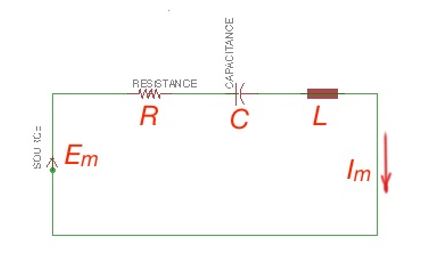
Let’s consider an AC circuit on the picture below. The Kirchhof equation can be created for this scheme. In this equation we will replace current i with the current magnitude , the voltage on the resistor will be , voltage of the inductor will be , and capacitor voltage is:
The multiplier in these equation is caused by the differently phase-oriented circuit elements according to the current orientation.
can be presented as , or Then .
This method is called symbolic method, and it uses the images of complex numbers.
The multiplier is a complex number that represent resistance on the complex plane, measures with Ohm, and is called complex resistance:
, so or .
It is called the Ohm law for the sinusoidal current circuits. Generally speaking complex resistance can be written in the following form , where is active resistance, is a reactive resistance.