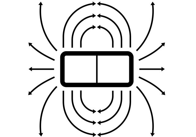
Often networks contain magnetic elements, for example coils, that can create magnetic induction in the other close placed coils, generating the self-induction EMF. Let’s consider two networks with series and parallel coils.
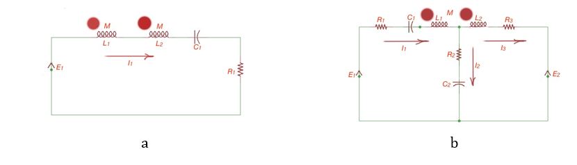
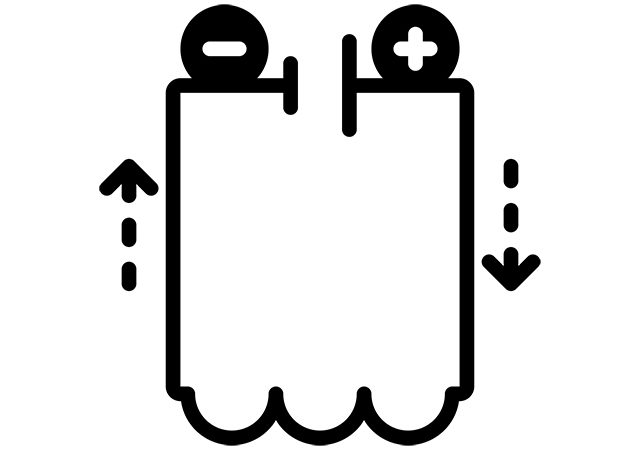
The magnet elements in a network can be connected matched or not matched. In the Figures above our magnet elements are connected matched. The currents equation for the loop a is: . For the second network , the first loop is , for the second loop .
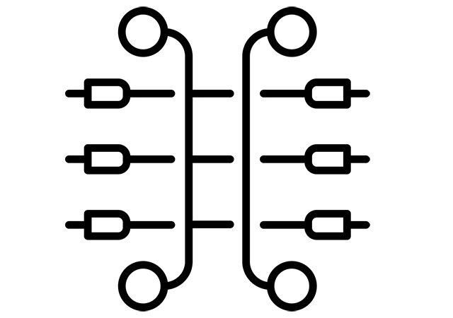
These equations correspond to Kirchhoff’’s currents Law and help to calculate currents in the network. Let’s consider the case when magnetic elements are connected, counter and matched, as is shown below.
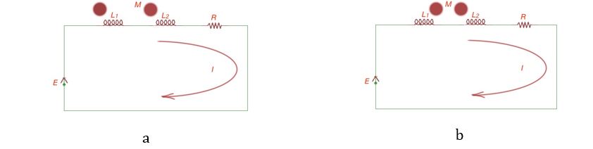
Here the currents equation will be , for the second circuit the currents equation will be . In complex form the first equation appears as: , where complex resistance .
In the complex form the second equation is shown as: , where the complex resistance . The popular method to calculate the mutual inductance of coils in a network is to measure the current, potential and power of the network, and calculate the resistances of the network.
For the counter connection, complex resistance , for matching connection complex resistance , their difference , then mutual inductance is .
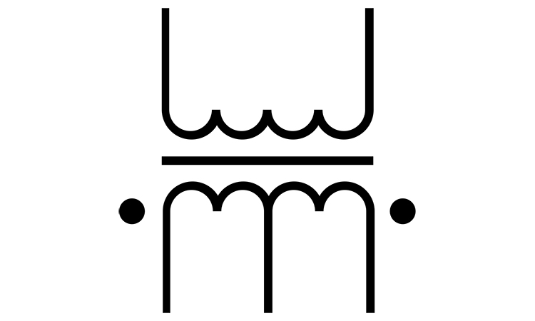
Let’s consider a transformer, the static device that transfers electro-magnetic energy between two or more circuits. The transformer is shown on the figure below.
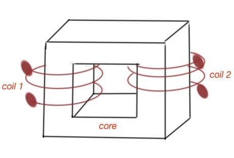
A transformer consists of the magnetic core and two coils with characteristics and . The magnetic permittivity of the transformer core is supposed to be constant. The mutual inductance of the transformer is . Let’s consider the simplest circuit with a transformer.
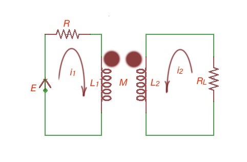
There are two loops. For the first loop , for the second loop .
The complex form of these equations is:
.