Complex conductance is the value, reverse to the complex resistance , where . Complex conductance is measured with , .
Ohm Law’s using the conductivity concept is . The current can be presented like where is an active consistent of current and is a reactive consistent.
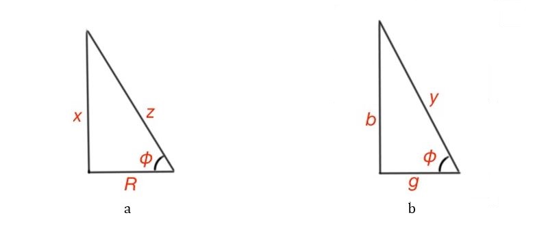
The module of complex resistance .
Here the z parameter is a hypotenuse, and are the sides of the triangle. The resistance triangle shows the relation between the active and reactive resistances. So active and reactive conductances are also related to each other with the triangle model, .
In accordance with the first of Kirchhoff’s Laws, the sum of all the currents of the node is equal to 0, i.e.,.
We can represent each current in a complex form so .
So it does mean that .
Let’s consider the second Kirchhoff Law regarding the example of the circuit containing the EMF element, resistor, inductance and capacitance. So .
The sums on the both sides of the equation can be replaced with:
This is a short form of the second Kirchhoff Law.
Note, that all the potentials of the AC circuit are complex numbers. Every element of the circuit has its complex potential. These potentials can be drawn on a plane, and the aggregate of all complex potentials on the plane are called a topographic diagram.
Active power of the electric circuit element is the average value of an instantaneous power value over the period of time T :
Let’s consider the current as and , then .
The active power is the heat dissipating in the element with the resistance in the unit of time, where.
It is measured with Watts (Wt). The reactive power of the piece of electric circuit is equal to the potential of the circuit element multiplied by the current of the piece of circuit and the sinus of angle between the potential and current, so .
It is measures with reactive. Let’s consider in detail what is reactive power in a piece of electric circuit in series with connected resistance , capacitance and inductance .
So we can see that reactive power consists of a static part and a dynamic part. The static part is organised at the beginning of the electric circuit excitation process and does not change any further. The dynamic part changes during the electric circuit process excitation.
The average reactive energy of the piece of electric circuit per the quarter of the period is.
This does mean that the load and generating elements exchange the energy twice per period. The total power , the active, reactive and total energies are connected by the relation where and are catheters and is hypotenuse.
Let’s consider the complex statement , and conjugated complex number
Let’s consider voltage at the electric circuit , current The power . Here is an active power, is a reactive power.