This post explains the difference between comparator and schmitt trigger. A comparator is a circuit with two inverting or non-inverting terminals and an output that varies from rail to rail. A comparator should have a low offset, high gain and high common-mode rejection.
Comparators can be an independent device or operational amplifier and can perform comparator functions. A comparator’s logic output indicates which of its two inputs has higher potential, and as a result is at one or the other rail. It also can switch between rails.
Operational amplifiers can perform these functions, but with some limitations. They should work only as closed-loop systems, and never be overloaded to its saturation characteristics. They are perfect for driving simple resistive or reactive loads.
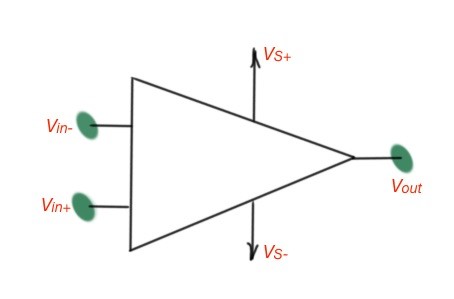
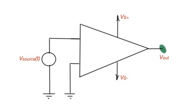
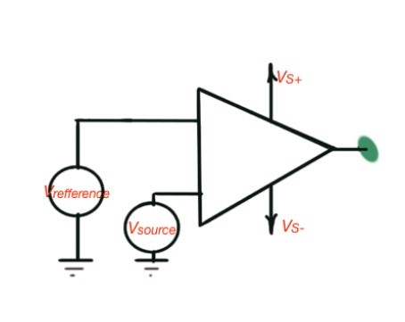
The difference between operational amplifiers and comparators themselves is the output, which is analogous for most operational amplifiers and logic for comparators. The schematic of the operational amplifier in the open-loop mode and operational amplifier as a comparator are depicted in Figure 1.
This circuit compares the input voltage with the ground level, and if the difference is positive the output signal is positive, and negative in the opposite case. Mathematically this function can be written as .
The input and output characteristics of an operation amplifier are depicted in Figure 2. The operational amplifiers are also designed to contain the reference voltage. The idea of reference voltage can be seen in the transfer characteristics of the operational amplifier circuit, depicted in Figure 3.
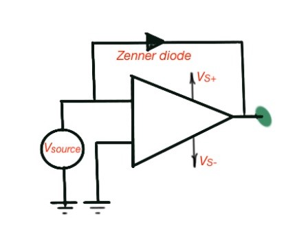
If we need to use voltage levels that are different from the fixed and voltage levels of the operational amplifier, we can add Zenner-diodes into the circuit. This scheme also reduces the switching time of the operational amplifier.
It is very important, because a comparator should form a very small switching time. The operational amplifier with Zenner-diode is depicted in Figure 4 and is called Zenner-clamp circuit. Modern operational amplifiers that serve as comparators are presented as independent integrated circuits (ICs), designed by many manufacturers.
 a
a
 b
b
Figure 1. Open-loop operational amplifier (a) and an operational amplifier as a comparator (b).
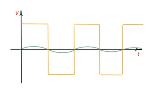
Figure 2. Comparator input and output characteristics.
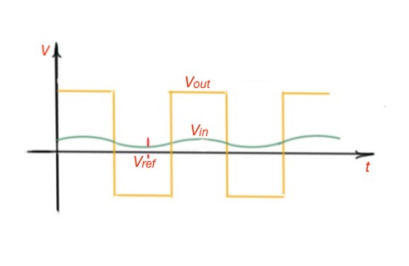 Figure 3. Comparator with reference voltage input and output characteristics.
a
 b
b
Figure 4. Comparator with reference voltage and a Zenner diode circuit.
One of the very frequent operational amplifier applications is detecting if the input voltage is reaching a certain threshold voltage level. In this case the operational amplifier is used in the circuit depicted in Figure 5, and this circuit is called the Schmidt trigger.
This circuit provides positive feedback and it improves the comparator’s performance. It is easy to show that the conditions of switching the trigger are the following: is the condition of switching from a positive to a negative state and the condition of switching from negative to positive level.
If we need the switching level to be other than 0, we must add a reference voltage to the scheme as shown in Figure 6. And the switching conditions will be and correspondingly.
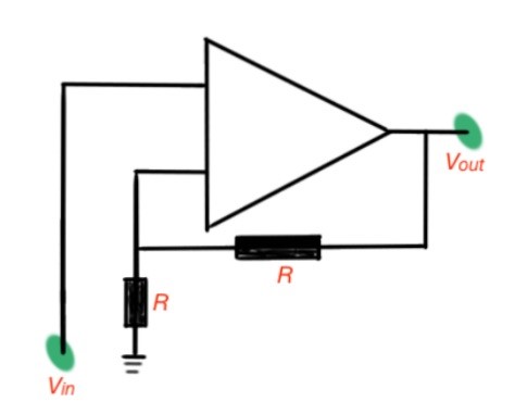 Figure 5. Schmidt trigger circuit.
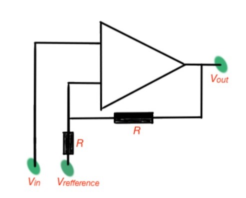 Figure 6. Schmidt trigger with reference voltage.
The operational amplifier can also perform timing functions. For this purpose, the operational amplifier can be used in the circuit shown in Figure 7, and is called a multivibrator. This circuit is generating the square signal with a fixed period and amplitude. The period of the result waveform can be found as .
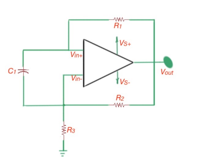 Figure 7. Multi-vibrator circuit.
More educational tutorials can be accessed via Reddit community r/ElectronicsEasy.