
Transformers are most frequent nowadays in the magnetic structures that are in use in many devices. The ideal transformer is a device that sets the AC voltage up or down with an exact coefficient. The ideal transformer is depicted below. The magnetic flux is concentrated in the core, and that flux links all turns of the coils, and permeability of the transformer is infinite.
The transformer is operated by the AC voltage, that generates some level of the MMF, creating the time varying magnetic flux linking the coils of the transformer. This time varying magnetic flux creates EMF at the coils – these are the operating principles of the transformer. We must remember that the ideal transformer demonstrates lossless process.
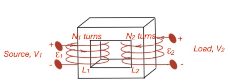
Let’s consider the transformer. In accordance to the Faraday’s Law the EMF .
Here index 2 symbolises the output EMF, or output voltage. Then i.e. the output voltage can be measured as the input terminal voltage multiplied by the ratio of the coil turns of the transformer.
The current induces the MMF , which is supposed to change the flux ϕ of the core. However, flux of the core does not change, as the MMF is compensated by the induced input current MMF . Then and . The constant is called the transformer ratio.
An ideal transformer does not dissipate power, so . Real transformers do not behave in this way. Real transformers perform resistances of the wires, current leakages, power losses and other losses mechanisms.
An important transformer parameter is power efficiency .
Electromechanical devices can convert mechanical energy to electromagnetic energy. The name of the device that can perform this function is an energy transducer. If the transducer converts electromagnetic energy to the mechanical one, it is called an actuator. If the transducer converts mechanical energy to electromagnetic energy, it is called a sensor.
The mechanism that allows the conversion of electromagnetic energy to mechanical energy is a piezoelectric effect. This consists of the electrical or magnetic strains in the crystals of the materials, which leads to the electric charge generation in the electric field. The transformation of mechanical energy to electromagnetic energy can be made by coupling the energy stored in the magnetic field.
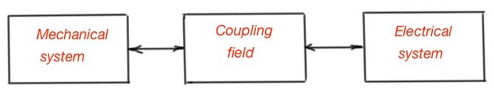
Let’s consider the electromechanical system that consists of the electrical part, mechanical part and the transforming part, making this transformation real. Figure below depicts how this energy coupling works. All three parts of the system are characterised by the losses – for the electrical system it’s resistance, for the mechanical system it’s friction, for the transforming part it is eddy currents and hysteresis losses.
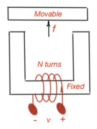
Electromechanical systems can also supply energy or store it. One of the types of transducers are moving-iron transducers, like solenoids, electromagnets and relays. The electromagnet consists of two parts – the fixed and movable part. The movable part can be displaced by the magnetic force. The equation of the energies in this system states that the small amount of energy is
The flux in this system depends on the coil current and the displacement of the movable part of the electromagnet. It does mean that .
Current and displacement are independent variables .
In order to simplify the analysis of an electromechanical system and calculate the energy stored in the magnetic field, let’s assume the system is magnetically linear. Then the energy of the magnetic structure is:
So from the formulas above we can calculate the force moving on the movable magnetic structure:
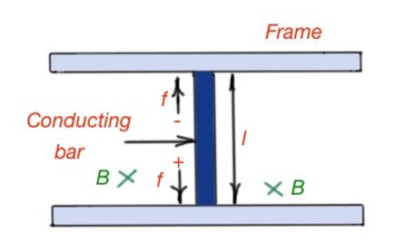
Another class of electromechanical transducers are moving-coil transducers. This class of transducers unites devices like microphones, loudspeakers, electric motors and generators. Let’s start from the magnetic force acting on the electric charge in the magnetic field . Let’s consider the transducer (below). Here a conducting bar moves between the fixed frame. The magnetic field, the forces and the velocity vector of the conducting bar directions are depicted below.
A moving–coil transducer can act as a motor. Here the motor is a moving coil-transducer, with an externally supplied current flowing through the conducting bar, displacing it to the given distance.
Let’s consider a small element of the moving-coil transducer as depicted below. Here the charge velocity in the current so .
Then , and . Then considering the equation for the electric charge in the magnetic field . In case the and are perpendicular to each other, the magnitude of the force is , if and have the angle between them, the magnitude of the force is .
Another class is a generator case, where the generator is a moving-coil transducer, which displaces the moving coil by the external fields converted into the EMF and thus into the electric current through the conducting bar.
Specifically, potential difference will appear on the conducting bar, as positive and negative charges are oppositely directed. This potential difference is the EMF, that is equal to the magnetic field force acting on the charges. So .
This formula works if , , and are mutually perpendicular. These vectors are not necessarily always perpendicular, and it makes the analysis a little more complicated, by including the correspondent angles to the equations. However, the most frequently used devices are constructed with the vectors , and mutually perpendicular to each other.
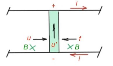
If we will consider the device depicted on the figure below, as a part of the system, there should be a current loop, formed by the conducting bar. The conductor moves to the right and generates the EMF, which then gives the current . At the same time there is a force of the magnetic field, affecting the conductor, directed left . So there should be an additional external force, , directed right.
The electrical and mechanical power for this ideal device is .
The considered transducer should be connected to the voltage source , some resistance , and inductance as a part of the electric circuit. The transducer should also be characterised by the elastic force . If the EMF is generated by the transducer then this device acts like a generator, if the EMF , then the device works like a motor.
Practical transducers are characterised by the inertia, friction, elastic forces, and also inductance, resistance and capacitance. Let’s assume that the friction coefficient is , the conducting bar mass is m and the elastic coefficient is . Then from a mechanical point of view .
From the electrical point of view
Then the conducting bar velocity and the current is .