This post is covering ADALM1000 SMU Training: voltage and current division. After the introduction of the SMU ADALM1000 let’s start with the first of some small, basic measurements.
Written by Doug Mercer, Analog Devices
Now let’s get started with the first experiment.
Objective
The objective of this lab activity is to verify the voltage and current division properties of resistor networks.
Background
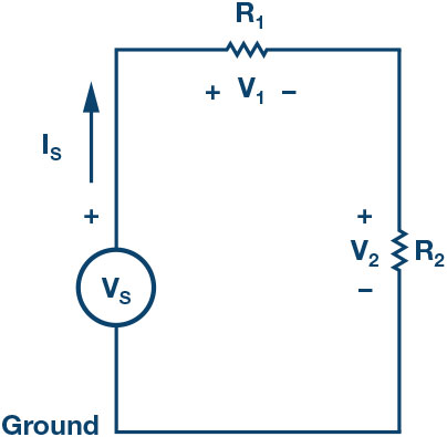
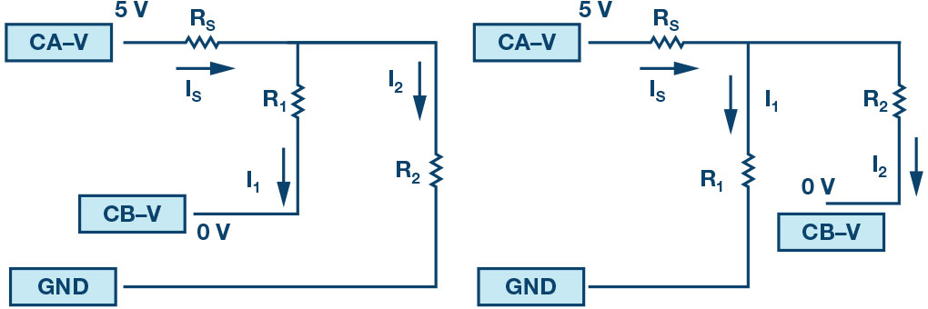
Voltage and current division allow to simplify the task of analysing a circuit. Voltage division allows to calculate what fraction of the total voltage across a series string of resistors is dropped across any one resistor. For the circuit of Figure 2, the voltage division formulas are:
Current division allows to calculate what fraction of the total current into a parallel string of resistors flows through any one of the resistors.
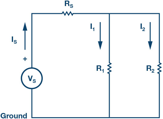
For the circuit of Figure 3, the current division formulas are:
Materials
- ADALM1000 hardware module with installed ALICE software (see the Notes section at the end of this article).
- Various resistors: 470 Ω, 1 kΩ, 4.7 k Ω, and 1.5 k Ω.
Procedure
1. Verify the voltage division:
a) Construct the circuit as shown in Figure 2. Set R1 = 4.7 kΩ, R2 = 5 kΩ, and use the fixed power supply 5 V as voltage source VS.
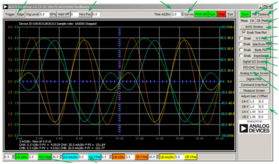
b) Use the ALICE desktop tool to measure voltages V1 and V2 with AWG Channels A and B in high-Z The rest of the settings do not matter at this point. Under the Curves drop-down menu select CA- V, CB-V, CA-I, and CB-I traces for display. Or just click on All to select all four traces.
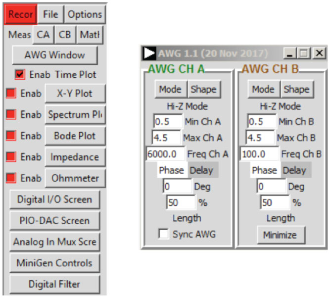
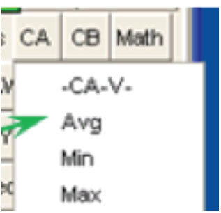
Under the CA and CB Meas drop-down menus, select Avg under the -CA-V- and -CB-V- sections to display the average voltages on each channel. Click on the green Run button to start taking measurements. The values will be displayed below the main grid.
Repeat this step for R1 = R2 = 4.7 kΩ and write down the measurements.
c) Calculate voltages V1 and V2 by using Equation 1 and Equation 2 in each
d) Compare the results from Steps 1a and 1b.
2. Verifying the current division:
a) Construct the circuit as shown in Figure Set R1 = 470 Ω, R2 = 1 kΩ, and RS = 470 Ω.
b) Use the ALICE desktop tool to measure the currents IS, I1, and I2. Connect the Channel A generator output as voltage source Set CHA to source a dc voltage of 5 V. Use Channel B as an ammeter to alternately measure I1 and I2 by connecting the lower end of R1 and R2 to Channel B with Channel B set to 0 V.
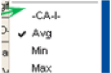
To display the average current in each channel, select Avg in the -CA-I- and -CB-I- sections of the Meas drop-down menus.
Repeat this step by using R1 = R2 = 470 Ω and write down the measurements.
c) Calculate the currents I1 and I2 by using Equation 3 and Equation 4.
d) Compare the results from steps 2b and 2c.
Questions
- How well did the measured outputs and calculated outputs compare? Explain any difference.
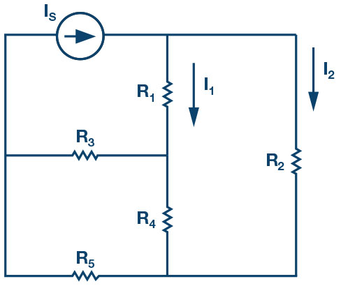
- Can you apply current division to obtain I1 and I2 for the circuit shown in Figure 8? Explain briefly.
Notes
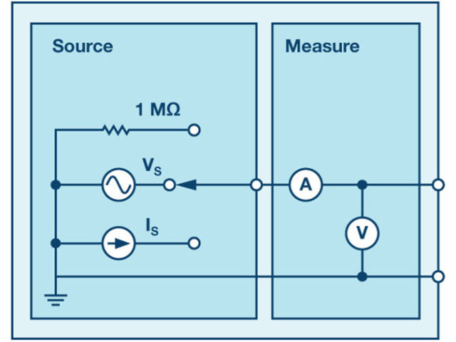
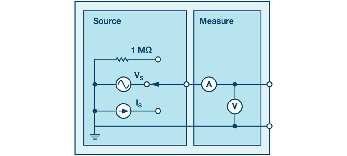
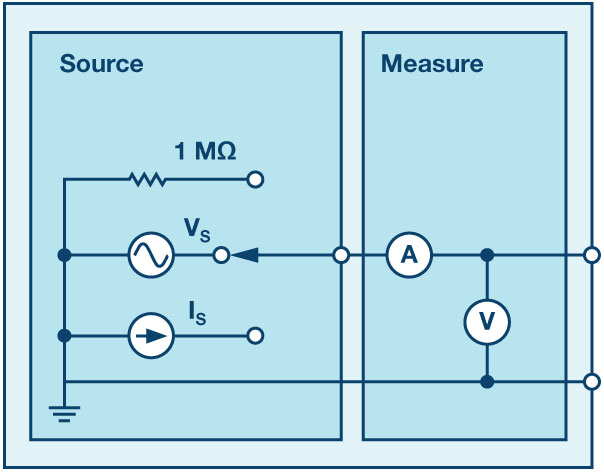
As in all the ALM labs, we use the following terminology when referring to the connections to the ALM1000 connector and configuring the hardware. The green shaded rectangles indicate connections to the ADALM1000 analog I/O connector. The analog I/O channel pins are referred to as CA and CB. When configured to force voltage/measure current, –V is added as in CA-V or when configured to force current/measure voltage, –I is added as in CA-I. When a channel is configured in the high impedance mode to only measure voltage, –H is added as CA-H.
Scope traces are similarly referred to by channel and voltage/current, such as CA-V and CB-V for the voltage waveforms, and CA-I and CB-I for the current waveforms.
We are using the ALICE Rev 1.1 software for those examples here. File: alice-desktop-1.1-setup.zip. Please download here.
The ALICE desktop software provides the following functions:
- A 2-channel oscilloscope for time domain display and analysis of volt- age and current
- The 2-channel arbitrary waveform generator (AWG) controls.
- The X and Y display for plotting captured voltage and current voltage and current data, as well as voltage waveform histograms.
- The 2-channel spectrum analyzer for frequency domain display and analysis of voltage
- The bode plotter and network analyzer with built-in sweep generator.
- An impedance analyzer for analyzing complex RLC networks and as an RLC meter and vector
- A dc ohmmeter measures unknown resistance with respect to known external resistor or known internal 50 Ω.
- Board self-calibration using the AD584 precision 2.5 V reference from the ADALP2000 analog parts kit.
- Alice M1K voltmeter.
- Alice M1K meter source.
- Alice M1K desktop tool.
For more information, please look here.
Note: You need to have the ADALM1000 connected to your PC to use the software.
Author: Doug Mercer, Analog Devices