This post answers the question: “What is line-commutated three-phase rectifier?”. As we know from previous post, these rectifiers are used to convert a fixed voltage, fixed frequency AC power supply into variable DC output. Input signal supply usually characterised by fixed RMS voltage and fixed frequency. Phase controlled thyristors in the rectifier are used to create controlled output (load) voltage and current. This is due to variable delay angle that can be controlled by gate current of thyristor. Line-commutated three-phase rectifier circuit is depicted on the scheme below.
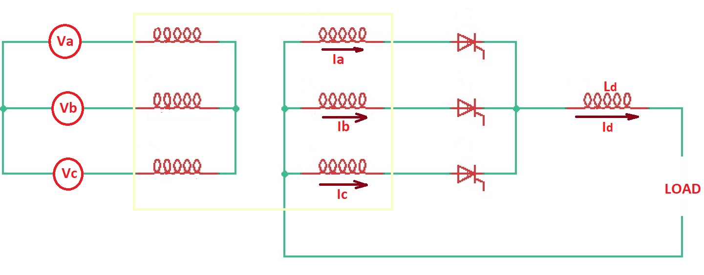
Here three-phase input voltage is supplied through the star connected transformer. Thyristors are in ON state when they are experiencing positive half-cycle of an input supply voltage. When the input voltage half-cycle is negative, the thyristors are in OFF state. The combination of three thyristors are here have common cathode configuration to control load voltage. Load voltage control can be made by applying positive anode-cathode voltage and gate current with the firing angle . In practice, due to commutation problems, the range of firing angle is . In controlled rectifiers usually natural commutation prociple is used.
Here when thyristor is ON (), voltage across the first winding is . When the thyristor is ON state (), thyristor goes reverse-biased or OFF state, voltage across the second winding is . When thyristor is ON state (), thyristor becomes reverse-biased and goes OFF state, so voltage across third winding is .
DC current and voltage forms for three-phase controlled rectifier are depicted below.
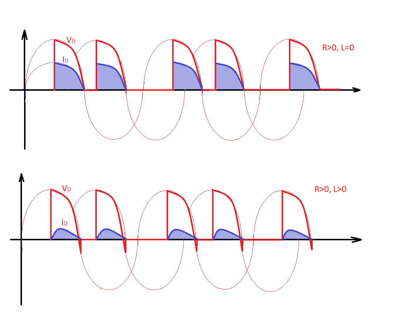
If load is resistive, then load current will have the same waveform as the load voltage.
The load voltage is . For this equation can be seen that if then load voltage is positive, when the load voltage becomes negative (the rectifier work as an invertor).
Summarising three-phase controlled rectifiers operate with three-phase AC supply voltage, they provide higher DC output voltage, ripple frequency and power.
Three-phase line-commutated rectifiers are used for DC motor control, AC traction systems, electrochemical and electrometallurgical processes, high voltage DC transmission, uninterruptible power supply systems and some other applications. Three-phase controlled rectifiers are used from the 15kW output power.
More educational texts are available at the Reddit community r/ElectronicsEasy.