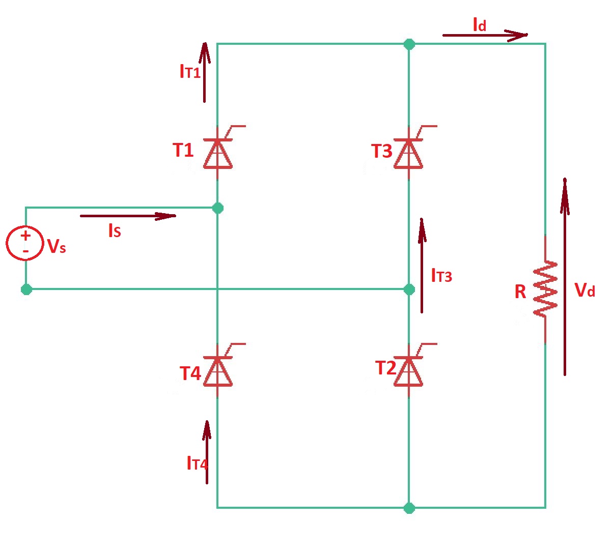
This post answers the question “What is line-commutated single-phase bridge rectifier?”. Bridge rectifier can be fully controlled with four thyristors and half-controlled with two thyristors and two diodes.
In case of fully controlled bridge rectifier with resistive load thyristors and are simultaneously conducting during positive cycle of source voltage . During the negative cycle of source voltage thyristors and are conducting simultaneously. The current from the schematic.
Let’s assume that rectifier has resistive-inductive load, with high inductance. Then the rectifier is a current source.
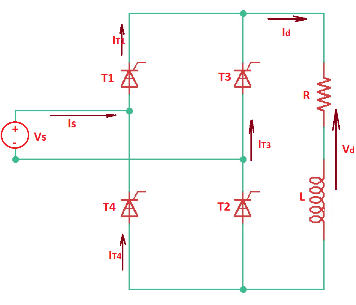
When the load current is through thyristors and are on even beyond the positive part of source voltage. Thyristors and turn off thyristors and and after commutation they can conduct load current. Average load voltage here is .
The supply current has the square waveform for continuous signal and it is shifted by the shift angle in accordance to the input voltage .
The maximum input current is n here is harmonic order.
is an RMS value. is the total harmonic distortion.If we have non-sinusoidal current, and sinusoidal single-phase supply then the active power is .
The full power is . Then the power factor is .
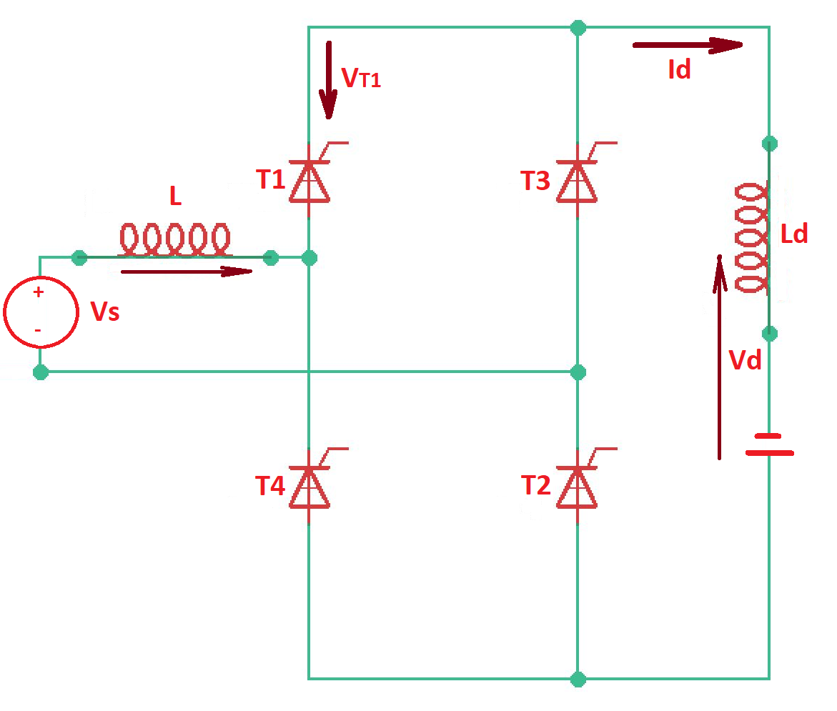
It is important to consider the process of commutation in bridge rectifier. Due to the presence of linear inductance in the circuit thyristors are not going off instantaneously, but characterised by the commutation angle (angular period when thyristors are sharing conduction), so and .
Let’s find commutation angle . During the commutation .
Then can lead us to . It means commutation angle is increasing when inductance or load current are increasing.
Process of commutation reduces the average load voltage .
Let’s consider situation when angle . In this case the load voltage can become negative., the power will flow back from the load to the supply. This operating mode is called inverting mode. Inverting mode can be obtained with the circuit below.
One of the most important applications of controlled rectifiers is uninterruptible power supplies. They are also can be used to generate DC voltage for the inverter. The input rectifier can serve as a battery charger. The rectifier output is usually filtered before to the load. The other application of controlled rectifiers is low power DC motor.
More educational materials can be found at the Reddit community r/ElectronicsEasy.