
An induction motor is a type of electric machine. Here the stator coils produce a magnetic field, and this magnetic field induces a current, producing motor torque. The main advantage of this machine is that it is as simple as a transformer, so there is no need for any additional excitation.
The rotor typically consists of a squirrel cage or wound rotor. The squirrel cage consists of short circuit conducting bars, and the wound rotor consists of the short-circuited multi-phase windings.
Here the induction motor operates by using the current generated by the stator field. The rotor usually does not require any external electrical connection. Induction motors operate with the speed dependent on the load. An example of an induction motor is depicted below.
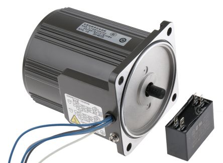
Panasonic M91 reversible induction AC motor
The speed of an induction motor is lower than the synchronous speed, , where s is the slip of the motor, which is the function of the load, and is the synchronous speed. Voltages of the rotor are induced at the frequencies called the slip frequencies. The speed of the induction motor rotor fields are , and the mechanical rotor speed is . The rotor field rotates with synchronous speed, while the rotor does not.
The Induction motor operation can be described by the following circuit.
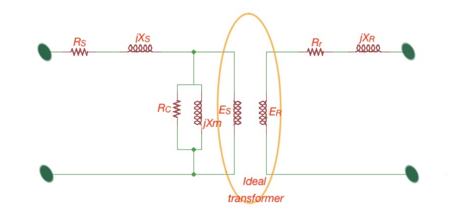
The electric circuit for the induction motor.
Here . is the rotor voltage when it is in a stationary state, , we can assume . So the rotor current is . The rotor parameters (current, voltage, inductance, resistance) can be expressed through the stator parameters. So the rotor resistance and reactance will be . So taking into account the transformation the equivalent circuit is depicted below. An equivalent circuit is very useful for determining the performance of the induction motor.
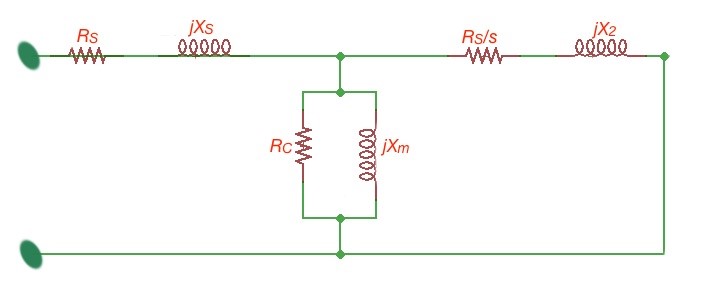
The circuit of the equivalent scheme for an induction motor.
In order to describe the inductor motor performance the torque speed can be very useful (Figure 4). There are a few points marked on the curve – the starting point, or breakaway torque; the next point is the pull-up torque, where the rotor starts to accelerate; the breakdown torque is the point where the torque becomes maximum. Two more points are 150% torque and rated torque. The general formula for average torque – speed characteristics of a steady-state inductor motor is: , is the amount of phases of the induction motor. Different types of induction motors are characterised with different torque-speed curves.
When the engineer is considering what induction motor to use, they should take into consideration the speed range, maximum and minimum speed levels, speed variation, acceleration and deceleration characteristics. The inductor motor is also characterised with the duty cycle and heating properties. The induction motor can also be characterised from the point of view of motional transients.
In order to provide stable and constant torque speed at inductance machines, there is a few methods that exist:
• Pole number control (the method where speed control is implemented by varying the amount of poles in motor);
• Slip control (the motor speed is dependent on the slip, the last one can be controlled by varying the motor voltage);
• Rotor control (the method where the rotor connects to resistors, that lead to the power losses and decreasing speed);
• Frequency regulation (it is possible to vary the inductor motor speed by changing the motor voltage frequency, if the motor supplies variable voltage).