This post tells about the parallel RC circuit analysis. RC circuits belong to the simple circuits with resistor, capacitor and the source structure.
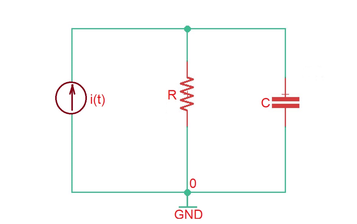
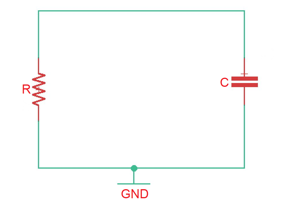
Let’s consider the circuit depicted on the figure below. We have to remember that even complex RC circuits can be transformed into the simple RC circuits. Here current source is the discontinued source.
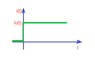
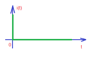
Let’s assume the following waveforms for and (depicted below).
Here the current . This is differential equation, that can be resolved as a sum of solutions: , where is a homogeneous solution and is a particular solution. The homogeneous solution is also called natural response (depends only on the internal inputs of the system). Particular solution is called forced response (depends only on external inputs of the system).
Resuming the process, from mathematics we know that, to resolve the differential equation above we have to follow 3 step procedure:
- to obtain homogenous solution ;
- to obtain particular solution ;
- to sum up particular and homogenous solutions to obtain total solution.
Let’s assume that homogenous solution for the equation is in the form of , where , so homogenous solution is . Here the plays important role, measured with dimensions of time and is called time constant of the circuit.
In order to find the particular solution we must resolve the equation . After simple mathematical simplifications we obtain the particular solution is .
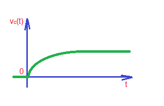
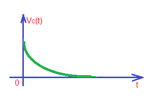
Total solution of the equation is . In order to find constant A we can apply boundary conditions : . From here we can get and . This function is depicted below.
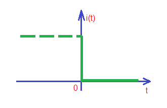
The case above explains how parallel RC circuit works during charging process. Now let’s consider the process of discharge of the circuit. Let’s consider the situation that the current source stopped supply, so our new circuit, and voltage and current waveforms look as depicted below with corresponding border conditions:
Our differential equation now . Let’s find homogeneous solution for this equation like in the previous case . Then we can find A constant , then for .
The solution for this transient process in general case depend on the border conditions and looks like for .
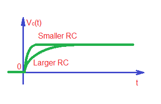
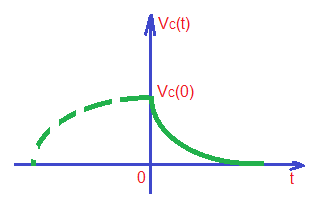
Current and voltage vaweforms for both processes combined are depicted below:
Educational content can also be reached via Reddit community r/ElectronicsEasy.