

This post tells about series RC circuit analysis. RC circuits belong to the simple circuits with resistor, capacitor and the source structure.
Let’s consider series connection of resistor and capacitor with the constant voltage source (circuit depicted below). Let’s assume that voltage source gives is continuous with constant amplitude V with waveform . And the capacitor at the moment of time was charged so .
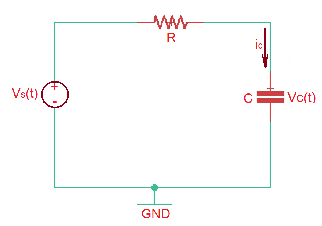
After applying KCL we will get the differential equation . As we already know how to resolve differential equations, let’s find homogeneous and particular solutions of the equation.
To find homogeneous solution we resolve equation . The solution will have the form , here is the time constant of the circuit.
Now let’s find out particular solution of the equation , the particular solution here is . Then total solution of the equation is . In order to find let’s use our border condition of , then .
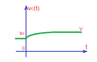
The total solution of the differential equation, the voltage through the capacitor is .
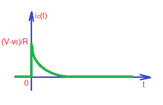
Current through the capacitor can be found by the formula . So .
The waveforms of the capacitor voltage and current are depicted below.
As we can see capacitor in the circuit does change the shape of input signal. For example, it’s easy to show that square-wave input signal will result in non-square pulse. And the form of the output signal will significantly depend on the relationship between input signal period and constant.
Educational content can also be reached via Reddit community r/ElectronicsEasy.


