Combinational circuits are the way to represent logic functions. A combinational gate is a function of the inputs, creating a specific output. Combinational circuits can be described with truth tables. If the combinational gate inputs correspond to valid input values, then the combinational circuit outputs will correspond to the valid output values.
The most important fact about combinational circuit – it’s output value depends on the input values.
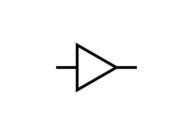
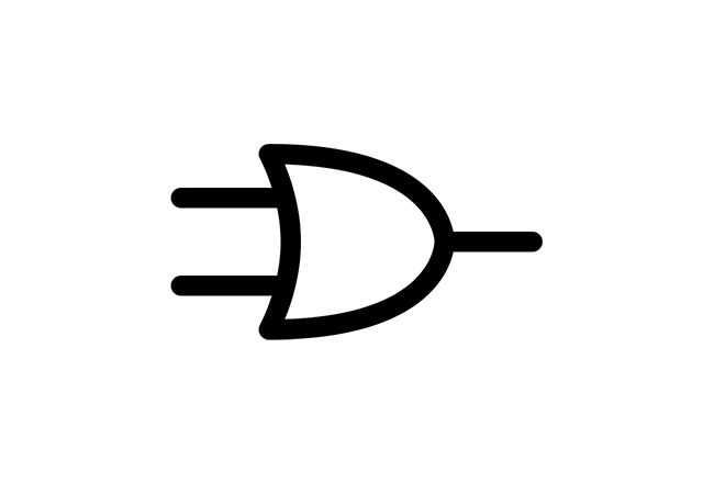
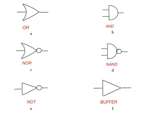
Here below some symbols that are used in the combinational logic.
Combinational circuit can have more then two logical inputs, or multiple inputs. Combinational circuits can also be simple or complex. Complex combinational circuits are combined with simple gates, using simple Boolean functions. Combinational circuit physically consists of real semiconductor components, and represent the logic function of the input, creating specific output value.
Table 1 shows the truth table for simple logical functions depending on the inputs.
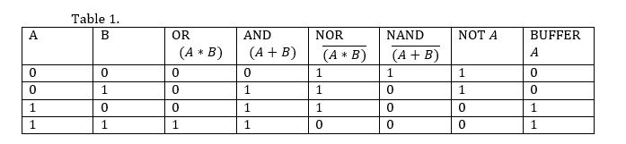
Figure 2 depicts the logic diagram for the function And this function can be represented in three ways: a. Using AND, OR and inverter functions; b. Using AND and NOR functions; c. Using AND, OR and NOR functions.
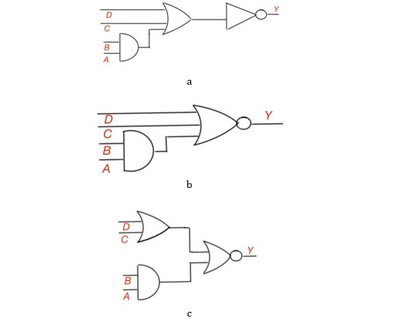
Figure 2. Three logic diagrams expressing logic function
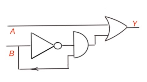
Figure 3. Logic diagram for function
Sum of products. Logic expressions simplification. Binary numbers.