Dielectric losses is the electrical power that is wasted by heating the dielectric in the electric field. Energy losses occur at the constant and variant current in the dielectric. As a practical matter, there is a value characterising ability of the dielectric to dissipate energy in the electric field. This is called tangent of dielectric losses. Tangent of dielectric losses is an angle, supplementing to 90 the phase shift φ, between current and voltage in the capacitance circuit. For an ideal dielectric δ is 0. The bigger energy dissipation in a dielectric, the bigger dielectric losses, angle δ and its tangent.
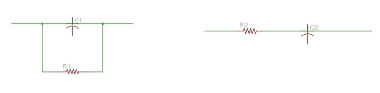
Let us consider a circuit equivalent to the dielectric capacitor with losses. It should be a capacitor with the resistor in parallel or in series. (Figure 31 a and b). These circuits are equivalent if the total resistance Z1 = Z2 = Z, and their active and reactive parts are also equal. This means their powers and energy loss angles are also equal. For serious circuits:
For AC voltage capacitance of a capacitor with big losses becomes a provisional value and depends on the equivalent scheme which has been chosen for a capacitor. The important thing is that parameters of equivalent schemes depend on the frequency. If losses in a capacitor is mostly driven by cross-cutting conductance, then losses can be found by the formula:
If losses result mostly via losses of wires, contacts and electrodes, then they can be found by the formula:
In the most cases loss mechanisms in a capacitor are complex, and losses (by the unit of capacitor value) can be found by the formula:
To describe interaction between electromagnetic fields and a compound we must use the complex permittivity parameter:
Let us define first Maxwell’s curl equation:
Big energy dissipation of the insulation dielectric leads to the insulation overheating and being destroyed.
Dielectric losses can be divided for four groups depending on their mechanism:
- Conductivity losses
- Relaxation losses
- Ionisation losses
- Resonant losses
Conductivity losses manifest themselves in the dielectric with significant volume or surface conductivity. If the rest of the mechanisms are not significant, and can be found using the parallel capacitor equivalent scheme (Figure 31a). Power loss does not depend on the frequency. Power losses and tangent loss are shown on the Figure 31 a and b.
Proportional coefficients for these equations depend on the material of dielectric.
Relaxation losses are the result of the active components of polarisation currents. It occurs in the region of high frequencies. Ionisation losses are inherent mostly in gas dielectrics. Resonant losses occur in some gases at some exact frequencies, expressed by strong energy dissipation. And also in solid dielectrics, when external frequency is equal to the natural atomic frequency.
Dielectric losses in gases in the electric fields, which are not strong enough for performing strike ionisation, are very small. The source of dielectric loses in gases can be conductivity. All the gases have small conductivity, and their tgδ is very small. At some exact level of voltage in a strong electric field, gas molecules are ionising, and ionisation losses turn on in a dielectric of the following power:
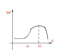
Ionisation losses also occur in solids, when there are gas impurities in a structure of a solid. tgδ starts to raise after some level of voltage Ui, and decrease after the level of voltage when all the gas molecules are ionised. (Figure 32). This graph is called an ionisation graph.
At high frequencies ionisation and losses increase, which can lead to the destruction of a dielectric. Air ionisation leads to the formation of ozone and nitrogen oxides. Losses for liquid dielectrics are diverse. For non-polar liquid dielectrics without impurities, all the losses are caused by conductivity, and its value is small. For polar liquids, losses can be notable, and are mainly dipole relaxation losses. Dipole relaxation losses in liquid dielectrics at high frequencies and AC voltage far exceed conductivity loss value. However, for low frequencies, they are quite small.
Dielectric losses in solids are multiple and diverse, as they have a different consistency and structure. Dielectric losses for solids with non-polar molecular structure are characterised by small losses. Dielectric losses in solids for polar molecular structure have big losses, especially with high frequencies, as mentioned above. Solids with polar molecular structure are organic compounds. Dielectric solids with an ionic lattice structure are dependent on the package of ions in the lattice. In solids with a dense ion package in a crystalline lattice without impurities, the losses are caused by conductivity and these are small. And at the high temperatures, conductivity losses occur. Solids with a crystalline structure and a non-dense ion package, are characterised by relaxation polarisation with high losses.