The world is currently in the midst of a technological revolution. With increasing level of tech integration into all parts of human life, innovation and ingenuity is more streamline than ever. Tools such as open-source software are easily accessible, allowing specialists to the general public to contribute together towards a better future. But behind every software change is a hardware functioning accordingly. So how do they work?
Objective : To understand the concept of capacitance
When cycling, skating, or skateboarding in a park, you have probably noticed that the surface is smoother and slipperier than compared to the road or soil. This is because at the micro level, the surface of the concrete laid area of the park has less ridges compared to a similar piece of concrete road. These ridges might be tiny but over a large area can make a different to how objects move over them. So how does this relate to electricity?
? The voltage and current output from mains power (from the wall plug) is an alternating current (AC). This means both the voltage and the current move in a wave like pattern between a high and a low signal. However, most household appliances, such as lamps, TVs, our mobile phones, all operate using a continuous high signal of voltage and current called direct current or DC. In order to convert from AC to DC, there are specialised converters to do the job for us. It is a complicated multi-step process in which, smoothening the ridges is an important step. This can be done with the help of capacitors! ?
Electrical energy and fields
To recall:
- Charge is a property of a particle.
- Current is the rate of flow of charge.
- Energy is the ability to do work.
- Energy cannot be created or destroyed but transferred from one medium to another.
- Voltage is the potential difference across a component or source of electricity.
- A voltage source is a type of battery that supplies a constant voltage to the circuit.
- A resistor is a component that restricts the flow of charge through a circuit.
- Magnetic properties: opposite poles attract and like poles repel
A resistor is a linear electrical component – that is to say, it has a proportional increase and decrease in the change of current and voltage. You were introduced to non-linear electrical components in the last article in the form of filament lamps and diodes. All these components are users of electricity. They take electricity and make use of it in others forms of energy such as light or heat.
Batteries on the other hand store electricity. They come in all shapes, sizes, and capacity to suit our everyday needs. In a way, they are similar to the internal storage of computers and mobile phones. But what if there is a need for short bursts of backup electric energy through a circuit? The idea of a capacitor is useful in such applications.
A capacitor is a component that can store electrical charge
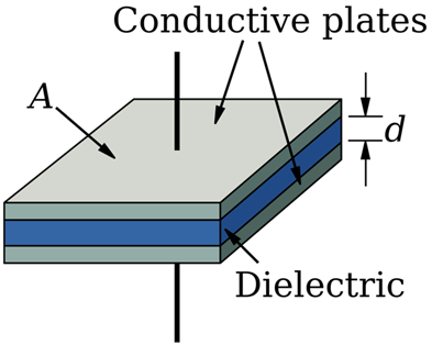
Capacitors are clever components that use the idea of electric fields to store energy. When two bar magnets are brought close to each other, the like poles always produce a force against each other, pushing them apart. The same principle applies to the internal structure of a capacitor. Two parallel conducting plates are placed along a plane with an even gap across them. This gap is filled with an insulating fluid called Dielectric.
? One of the primary needs for a dielectric is to prevent charge carriers jumping from one plate to the other. The capacitor power rating is often limited by the dielectric’s ability to insulate the two parallel plates and not break down! ?
The ability of a capacitor to store charge can be measured in a unit, called capacitance.
Capacitance is the ratio of the amount of electric charge stored to a difference in electric potential.
Capacitance is represented by the letter ‘C’.
The unit for Capacitance is Farad or ‘F’.
Q = charge
V = voltage
C = capacitance
It is important to note that one Farad is a huge amount of energy. Most household applications use capacitors with capacitances in picofarads (1 pF = 1.0 × 10⁻¹² F) and microfarads (1 μF = 1.0 × 10⁻⁶ F).!
To calculate the exact rate of charge for a charging and discharging capacitor, two equations can be derived using voltage, current, resistor, charge, and capacitance relationships. This is further elaborated in an advanced article on capacitance.
How capacitors work
As previously mentioned, a capacitor contains two parallel conductive plates separated by a dielectric. Like a power source, capacitors are placed across components. When the circuit is powered on, charge carriers flow along the circuit, through power-consuming components and back to the power source to complete the circuit.
In the capacitor branch, the pre-existing charge carriers in the wire and positive end of the capacitor are energised. Although charge carriers are unable to flow through the branch, they had to discover the “dead end” by travelling to the capacitor.
You can think of the circuit as a multi-lane motorway which only moves in one direction. There are no U-turn opportunities but there are roads that branch off from the motorway and back onto it.
The flow of positively charged charge carriers onto one end of the capacitor creates a net-positive charge on that end of the capacitor. The charge carriers on the opposite conductive plate start to experience a magnetic field force pushing them away. As more charge carriers build up on the positive plate, some charge carriers are pushed away from the opposite plate, along the wire and eventually onto the main branch, to the power supply’s negative end. This produces a net-negative charge on the opposite conductive plate. The capacitor is said to be charging.
Looking at the bigger picture, charge carriers are flowing into the positive end of a capacitor and flowing out of the negative end of a capacitor, hence completing a circuit!
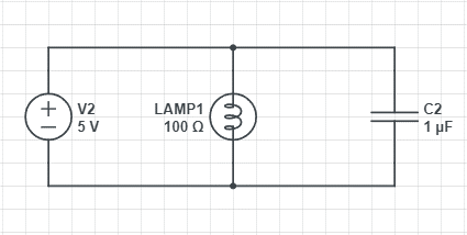
The diagram shows a simple test circuit to illustrate the use of a capacitor. During this time, the voltage per charge carrier increases till the capacitor is saturated.
The following is an equation used to calculate the charge over time, or current of a resistor-capacitor circuit in series.
Q(t) = charge over time
V = voltage
C = capacitance
R = resistance
As the circuit has been turned on for a long period of time, the capacitor branch starts to saturate with charge carriers. No more charge carriers can flow into that branch on the positive side and leave the branch on the negative side. The capacitor turns into a “roadblock”. Charge carriers only flow through the lamp and back to the power supply. In this state, the capacitor is said to be charged.
Now lets assume the power supply is turned off. The capacitor takes over to act as the secondary supply to keep the lamp lit. To do this, the surplus of charge carriers saturated on the positive conductive plate do not feel the magnetic force pushing against them due to the lack of charge carrier flow. This creates a concentration gradient between the positive plate and the lamp. As a result, highly energised charge carriers reverse the direction of charge flow and move in the opposite direction to towards the power supply and into the lamp. The capacitor is in its discharging state.
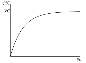
Charge carriers flow through the lamp to release energy in the form of light (and heat) then return to the negative conductive plate of the capacitor. Loss of energised charge carriers from the positive plate and build-up of discharged charge carriers on the negative plate decreases the concentration gradient of charge across the capacitor, eventually reaching equilibrium. The diagram below demonstrates the energy per charge carrier over time.
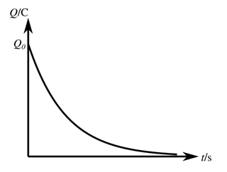
The following is an equation used to calculate the charge over time, or current of a resistor-capacitor circuit in parallel. This is similar to the circuit of the lamp above.
Q(t) = charge over time
Q0 = initial charge
C = capacitance
R = resistance
As mentioned, an in-depth derivation and further elaboration of the structure and calculations related to capacitors is available on our website.
Example: An electrician is diagnosing a circuit board of a fault. He knows the voltage through a particular branch is 10V and the branch contains a capacitor rated at 10mF. What is the current along the branch?
| Write down the formula to calculate the capacitance. This will guide you throughout the question. | |
| Rearrange the formula to make Q the subject. | |
| Substitute values in the formula.
(It is important to convert millifarads to farads) |
|
| Calculate the total charge. | |
| Use the formula of charge and time to find current. | |
| Substitute values in the formula
(as no value for t is given, it is assumed to be 1 second) |
|
| Calculate the value of current to find the final answer.
Always add the unit! |