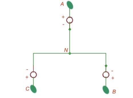
Three-phase circuits of voltage supplies are the three connected voltage supplies, with the same magnitude of amplitude and frequency, but shifted to 120 grad. A typical three-phase circuit is depicted on the figure below. The N shows the neutral point tied to ground.
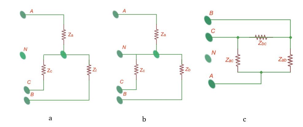
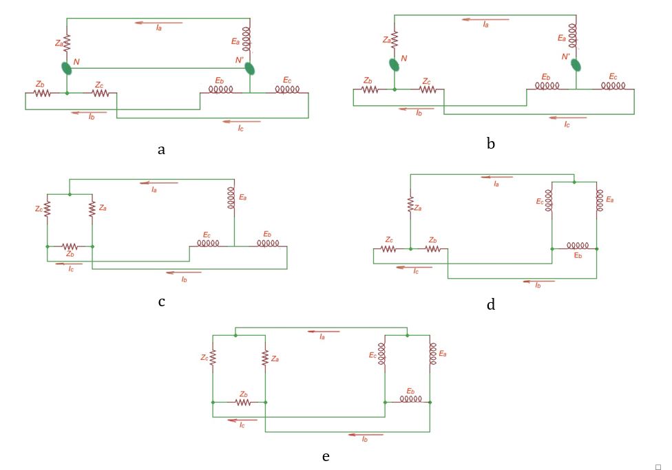
There are various ways of load connection to the neutral point, depicted on the figures below labelled a-c. There are five simple types of connection of a three-phase generator to the three-phase load, depicted on the figures below, labelled a-d.
Let’s think that positive current direction is from the source to the load. The wires, connecting the source and load are called linear. Currents and voltages through linear wires are called linear currents and linear voltages – and . Every generator coil is called a phase. Every load of the generator coil is called phase load. Currents through this load are called phase currents, voltages – phase voltages, and .
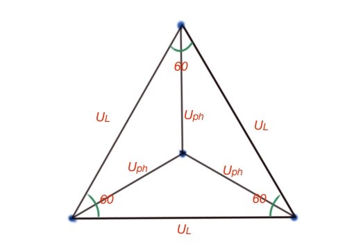
The phase and linear currents and voltage relationships depend on the generator connection scheme – star or delta. When the generator is a star connection, voltages are . When load is star connected currents are . When a generator is delta connected, and when a load is delta connected, the currents can be calculated by Kirchhoff Law. Figure below depicts the idea of the phase and linear voltages with the delta or star interconnection.
Let’s consider a few examples of the three-phase circuits calculation. We must remember that three-phase circuits are the circuits with sinus current. It is necessarily to keep in mind the operator of a symmetrical system . These two operators are moving a vector to angle.
On the figure above, labelled a, . If the load is distributed and , then . If the load is not distributed the . and the voltages and currents of the delta branches can be calculated by Kirchhoff’s Law.
Active power of a three-phase circuit P is the sum of the active power of the phase load and active power of the neutral wire. The reactive power of the three-phase circuit is the sum of reactive power of the phase load and a neutral wire. The total power can be seen as . To measure active power of the circuit with a neutral wire it should be used with three wattmeters; to measure active power without a neutral wire it should be used with two wattmeters.
When we put a sinusoidal current through a coil, the magnetic rotating field induces and concentrates around the coil core. The magnetic field vector has different directions in every single moment of time. When we have three coils, connected like a star with angle shift between them, the sinusoidal current through the coils induces the circled rotating magnetic field.
If the magnitude of the current or the frequency through one of the coils is different, the inducing magnetic field is an elliptical rotating field. In circuits where coils are inducing the self-induction, it should be taken into account with the calculation we considered before.