Written by Doug Mercer, Consulting Fellow, and Antoniu Miclaus, System Applications Engineer, Analog Devices.
Objective
The objective of this lab activity is to design a differential temperature sensor circuit using diodes.
Background
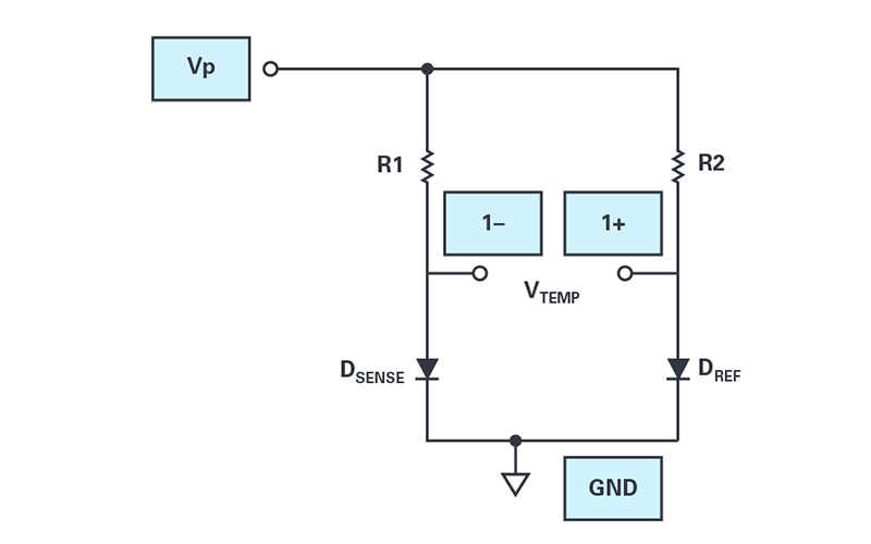
A diode’s forward voltage drop, VD, decreases by approximately 2mV for each 1°C increase in temperature, assuming a constant current in the diode. The circuit shown in Figure 1 uses this property as the basis of a crude differential temperature sensor. It is best if the diodes are of the same type and ideally from the same manufacturer. Both diodes are forward-biased, using equal resistor values to establish the same current, at least when the diodes are at the same temperature. Diode DSENSE serves as the temperature sensor, while diode DREF serves as the temperature reference maintained at a constant temperature – say, at room temperature (25°C), which is convenient. The difference in diode voltages VTEMP is consequently proportional to the difference in temperature.
Materials
- ADALM2000 active learning module
- Solderless breadboard
- Two 1kΩ resistors
- Two small signal diode (1N914 or similar)
Directions
Construct the circuit of Figure 1 using two 1N914 diodes.
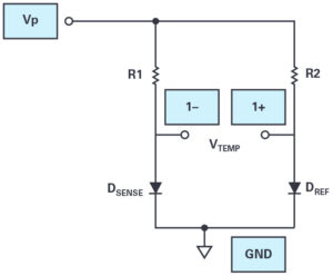
Figure 1. Differential temperature circuit.
Hardware setup
Connect scope input 1+ to the positive terminal of VTEMP and connect scope input 1– to the negative terminal of VTEMP. Use scopy voltmeter or oscilloscope instruments to monitor the value of VTEMP using the True RMS measurement display. Use auto-range for the voltmeter or set the Volts/Div scale for the oscilloscope to its most sensitive value (10mV) and ensure that Channel 1 is enabled. Connect Vp to the 5V power supply.
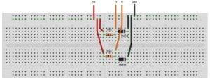
Figure 2. Differential temperature breadboard circuit.
Procedure
Step 1
Allow both diodes to reach the same temperature: TSENSE = TREF. Measure and record the voltage offset as TAMP set; subtract this offset voltage from your later measurements.
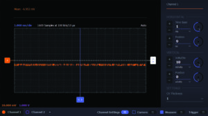
Figure 3. TSENSE = TREF differential temperature waveform.
Step 2
Heat the sensor diode by squeezing it between your fingers. Wait for the voltage to stabilise, subtract VTEMP set, and then record this value as the body temperature voltage. You might also try blowing through a straw to direct your warm breath at the sensor diode.
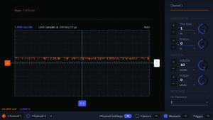
Figure 4. TSENSE > TREF differential temperature waveform.
If available, wrap the sense diode in a thin plastic bag and submerge it in ice water to chill the sensor diode. Again, wait for the voltage to stabilise, subtract VTEMP set, and then record its value as the freezing point of water voltage.
Determine the sensitivity of the temperature sensor output VTEMP in millivolts per °C.
Questions
- Can you derive the sensitivity in mV/°C you measured from the diode equation?
- What is the purpose of the reference diode in this configuration?
Find the answers on the StudentZone blog page on the Analog Devices website, here.