Any electronics students and hobbyists need, at some point, to upgrade their hardware and start using equipment such as signal generators, oscilloscopes and logic analysers. These standalone instruments might cost a fortune (usually hundreds, if not thousands of dollars) and require large spaces for usage and storage.
Written by Antoniu Miclaus and Doug Mercer
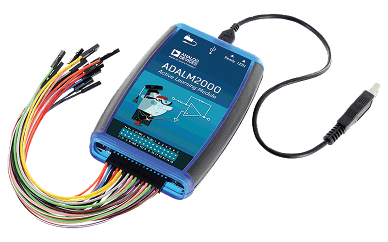
This is where ADALM2000 steps in. It is an affordable, USB-powered source measurement unit that expands the capabilities of the ADALM1000 active learning module (for more information and applications with ADALM1000, you can check our previous StudentZone articles).
The easy to use ADALM2000 active learning module is designed for students and hobbyists at all levels and from all backgrounds. It can be used for both instructor-led and self-directed learning to explore signals and systems into the tens of MHz and build a foundation when pursuing science, technology, or engineering degrees — all without the cost and bulk associated with traditional lab gear.
The module contains 12-bit ADCs and DACs running at 100 MSPS, bringing the power of high performance into a small device that can fit in a shirt pocket. With more than the combinations of a few parts, to understand the capabilities of the unit, the users must understand the fundamental operation of each part inside the unit.
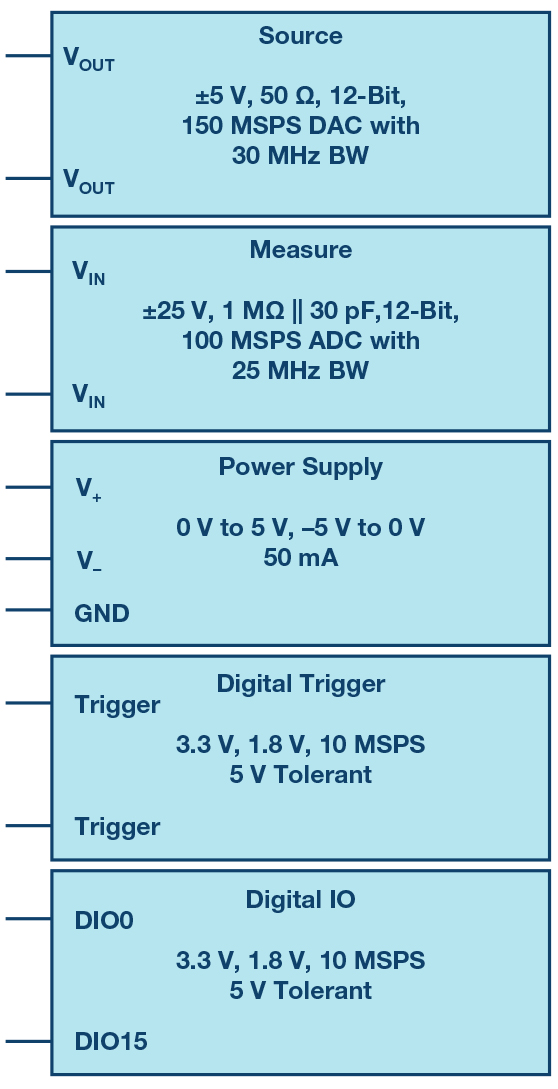
The hardware module contains the following features:
- USB 0 device and OTG (LAN and Wi-Fi supported)
- Two general-purpose analogue inputs:
- Differential, ±25V, 1MΩ || 30pF, 12-bit, 100 MSPS ADC with 25MHz bandwidth
- Two general-purpose analogue outputs:
- Single-ended, ±5V, 50Ω, 12-bit, 150MSPS DAC with 30MHz bandwidth
- Two variable power supplies
- 0V to 5V, –5V to 0V, 50mA
- 16 digital input or output pins
- 3V, 1.8V, 100 MSPS, 5V tolerant
- Two digital triggers
- 3V or 1.8V, 100 MSPS, 5V tolerant
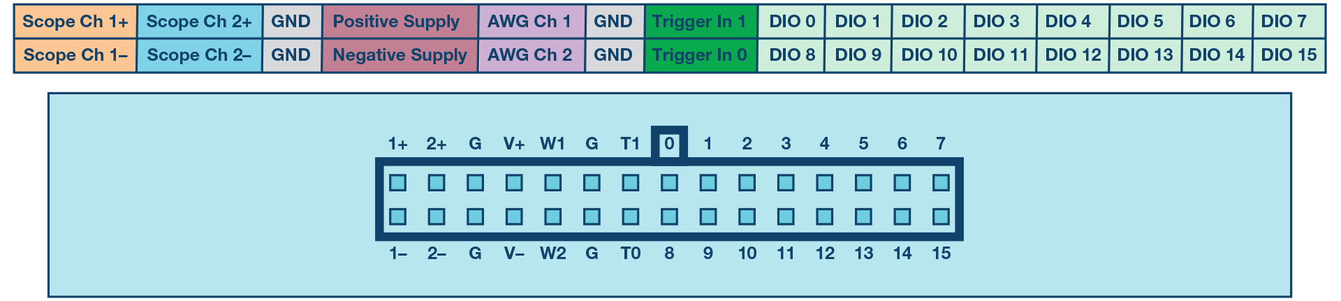
The access to the hardware unit is made through the output pins of the device presented in Figure 3. The module comes with 2×15 coloured cables to ease the separation between the module’s parts.
What about software?
The ADALM2000 works as a portable lab that, when used with a host PC, can augment classroom learning. Analog Devices’ Scopy software package supports the ADALM2000 and provides an intuitive graphical user interface (GUI) so students can learn faster, work smarter, and explore more. Scopy is built on open-source technology, which allows anyone to examine its source code and add new features.
Scopy uses the ADALM2000 features to create:
- Voltmeters
- Digital oscilloscopes
- Spectrum analysers
- Power supplies
- Function generators
- Arbitrary waveform generators
- 2-port network analysers
- Digital logic analysers with bus analysers
- Digital pattern generators
- Digital static inputs/outputs
Detailed information about how to use each of the instruments can be found on the Scopy wiki page.
What can I do with ADALM2000?
A series of lab applications are available for student use in electronics and connected knowledge areas, including communications circuits, power management circuits, and others. All the resources and examples are available on Analog Devices’ activity material page for ADALM2000. You can also check the EngineerZone education section for new blog posts on ADALM2000/ADALM1000/ADALM-PLUTO.
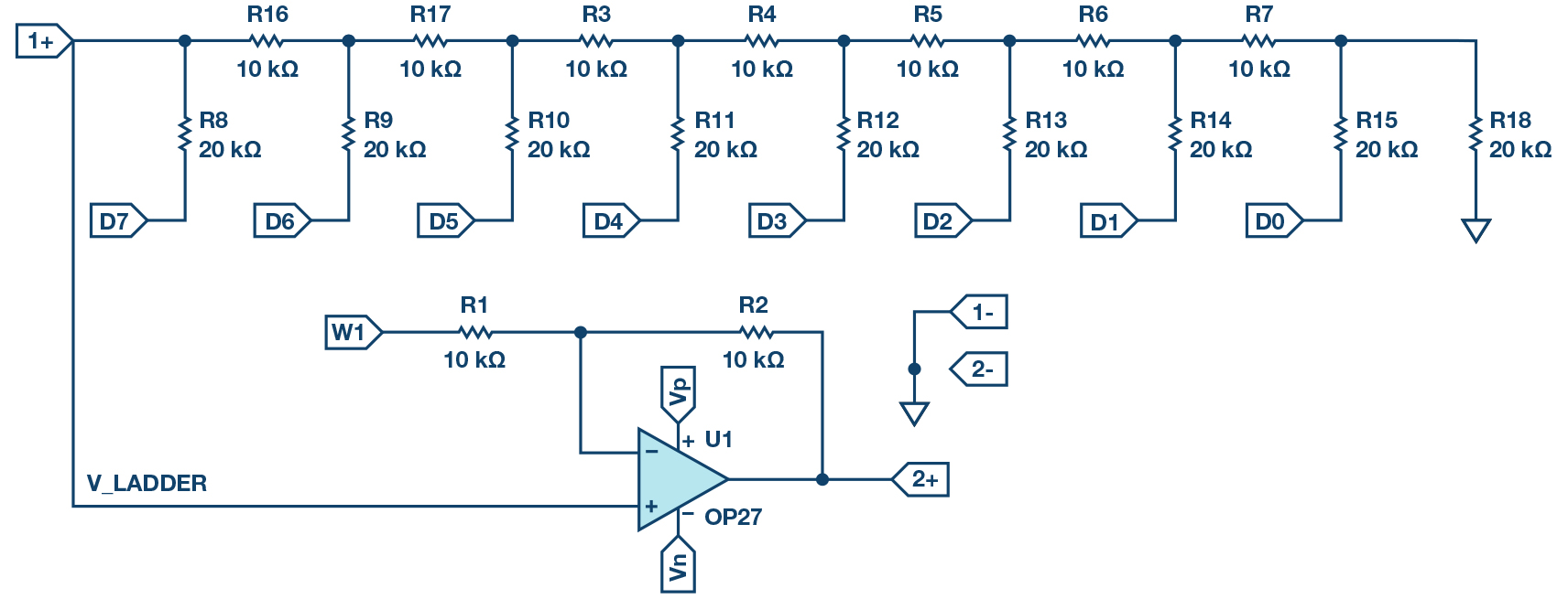
We will start our journey with a basic activity on analogue-to-digital converters, exploring both the digital and analogue parts that the ADALM2000 module has to offer. One of the most common digital-to-analogue converter block structures is the R-2R resistor ladder network, which uses resistors of only two different values, having a ratio of 2:1. An N-bit DAC requires 2N resistors.
When used in voltage mode, the legs of the R-2R resistor ladder (shown in Figure 5) are driven to one of two reference voltage levels based on the digital code D0-7, with Digital 0 representing VREF– and Digital 1 representing VREF+. Depending on the digital input code, VLADDER (shown in Figure 5) will be some fraction of the difference between the two reference levels. The negative of the two reference voltages (VREF–) is often ground (0 V). The positive reference voltage (VREF+) in our case here will be the positive supply (3.3 V).
Materials:
- ADALM2000 active learning module
- Solderless breadboard
- Jumper wires
- Nine 20kΩ resistors
- Nine 10kΩ resistors
- One OP27 amplifier
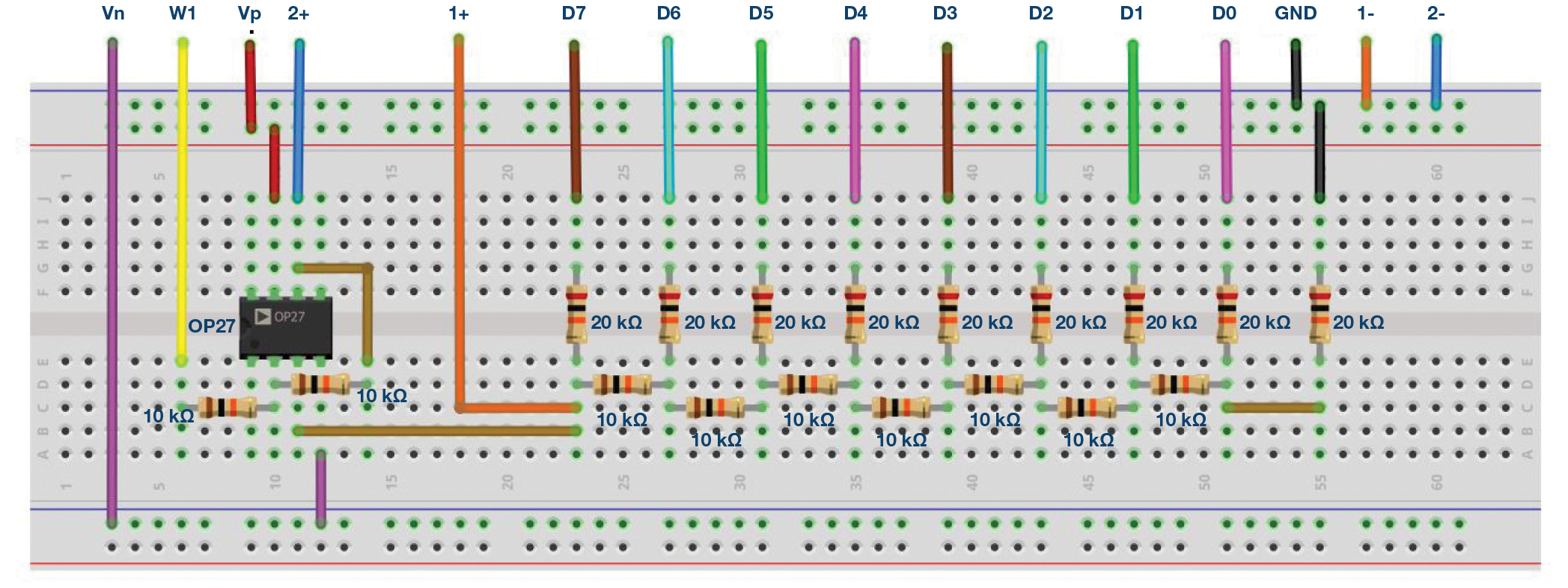
Build the 8-bit resistor ladder circuit shown in Figure 6 on your solderless breadboard. Connect the eight digital outputs, the scope channel, and the AWG output to the resistor ladder circuit as shown. Remember to connect power to the op amp supply pins.

With both R1 and R2 installed, set AWG1 to a dc voltage equal to the VREF+ of the DAC, which will be the +3.3V supply voltage of the CMOS digital outputs. This will produce a bipolar output voltage which will swing from –3.3V to +3.3V. Disconnect AWG1 and remove resistor R1 for a unipolar output voltage that will swing from 0V to +3.3V. Start the Scopy software. Open the Pattern Generator instrument. Select and group DIO 0 to DIO 7.
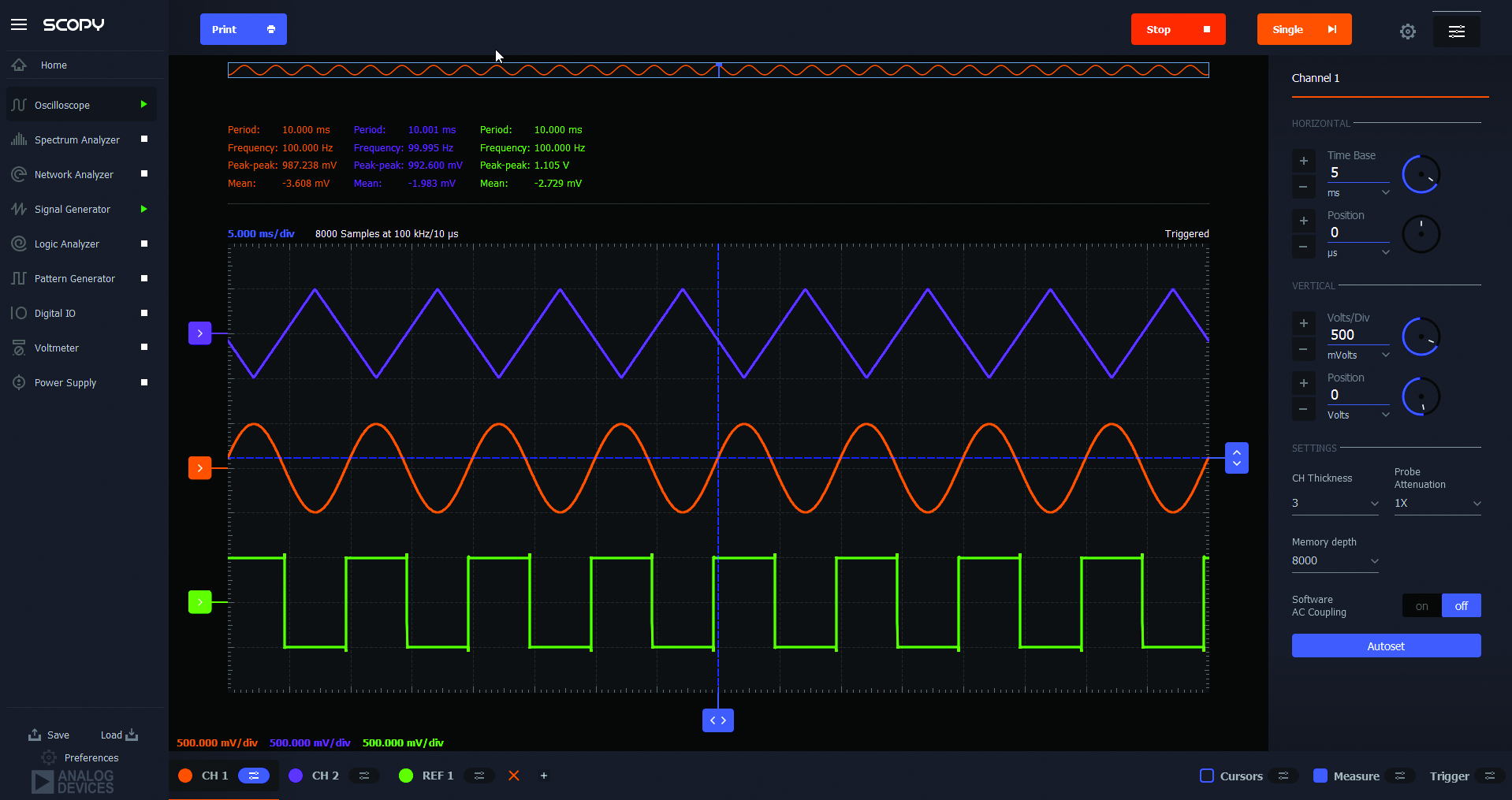
Now edit the parameters. Set the pattern to Binary Counter. The output should be PP (for push-pull). Set the frequency for 256 kHz. You should see something that looks like the screen in Figure 7. Lastly, hit the Run button.
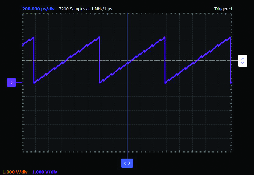
Open the oscilloscope instrument, turn channel 2on, and set the time base for 200μs/div. Be sure to hit the green Run button. You may also need to adjust the vertical range for the channel. 1V/div is probably good to start with. You should see (Figure 4) the voltage ramp up from 0V to 3.3V. The period of the ramp should be 1ms.
Change the digital pattern. You can try, for example, the random pattern or load custom patterns by making a plain text *.csv file with a column of numbers ranging from 0 to 255 (for the 8-bit wide bus). Here are some premade waveform files that you can load and try as custom pattern: sine, triangle, gaussian, etc.
Questions:
- Using Ohm’s law and the formula for resistors in parallel, what is the output voltage of the R-2R DAC for each reference voltage level (0V and 3V) applied at the inputs D7 and D6? Please present the results as a table.
- How much current will flow through this resistor network when input D6 is connected to 3V and D7 to ground?
You can find the answers at the StudentZone blog.