
This post answers the question “What is a series RL circuit?”. It shows how to make an analysis of series circuit with the step input signal.
The circuit and the input voltage signal are depicted below. Let’s find voltage and current wave-forms of the inductor and it’s time constant.
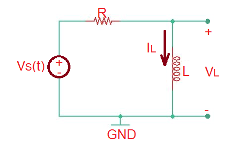
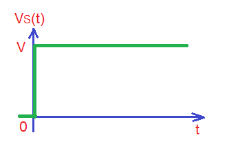
Let’s consider the voltage source signal as .
As in the example with the series RC circuit, we must apply KVL . The total solution of this differential equation is the sum of homogenous and particular solution.
In order to find homogenous solution we must resolve the equation . Let’s assume that homogenous solution is in the form . So , then and the homogenous solution is .
In order to find particular solution, we must resolve the equation . Particular solution of this equation can be . In this case .
So total solution is . Knowing that for , then . Then .
Here we can obtain .
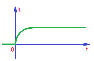
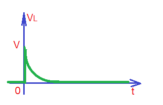
The current and voltage waveforms for inductor are depicted below.
Educational content can also be reached via Reddit community r/ElectronicsEasy.