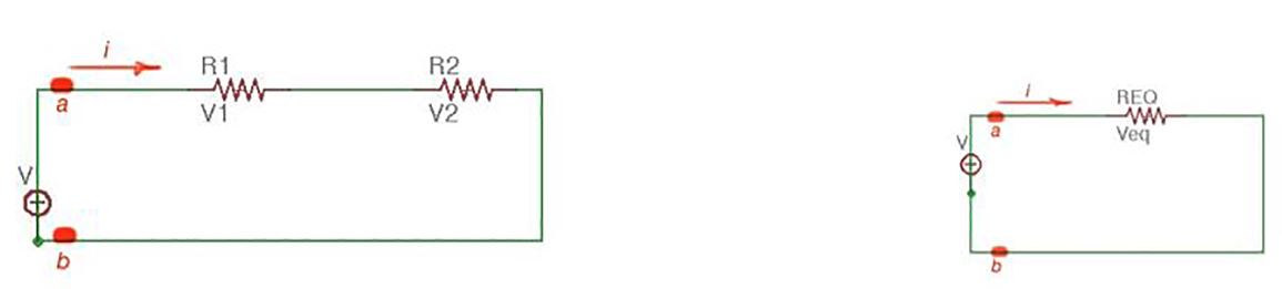
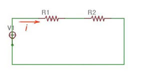
Let us take two resistors and in series and voltage source (figure below). Resistors are in series here and create a single-loop with the source . The same current flows through all of them.
According to Ohm’s Law for resistors:
According to Kirchhoff’s Law for the loop, we get the following:
Then:
, where
Current through the loop:
Voltages for each resistor:
We can assume that resistors and can be replaced by an equivalent resistor . And the loop can be replaced by an equivalent loop (figure below).
We can conclude that the number of resistors connected in series behave as an equivalent resistor, whose resistance is a sum of these resistances.
For resistors in series:
And voltages for each resistor are:
Voltage drop on the resistors in the serial network are not the same for different resistors, it divides according to the value of resistance. The bigger resistance, the bigger voltage drop. This principle is called voltage division. The circuit on the figure below is called the voltage divider.
Voltage and current division - equivalent resistance for parallel connection