
Written by Jeff Smoot, VP of Engineering at CUI Devices.
There are many types of encoders. In this blog post, we will focus on panel mount rotary encoders, explaining how they fundamentally work, along with key specifications and considerations. Rotary encoders can be defined as transducers designed to turn a rotational displacement into an electrical signal which can be read by the host system. An encoder sends out pulses as it is rotated a certain number of degrees, which can be read by a control device and used to determine direction, position, count or speed.
What are panel mount encoders?
Panel mount encoders are a type of rotary encoder, which as their name suggests, are physically mounted on panels. They are primarily used for human interface purposes. A volume knob on a stereo is an example. Panel mount encoders give the user the ability to control various system parameters by providing the link between the user and the system processor.
Panel mount rotary encoders are similar to potentiometers, another panel mount component used to translate rotational movement into a readable signal. However, panel mount encoders tend to have tighter manufacturing tolerances, which lead to improved accuracy and consistency. Secondly, panel mount encoders and their digital outputs are more compatible with today’s digital devices and require no analogue to digital converters, reducing cost and preventing errors.
Panel mount encoder applications
Panel mount encoders are used in many applications across numerous industries, including defence and aerospace, medical, consumer goods, and test and measurement to name a few. Some more specific use case examples could include cockpit controls, studio mixers and audio equipment, electronic lab and instrumentation, motor drives, and much more.
Key panel mount encoder specifications
There are several key specifications to consider when talking about panel mount rotary encoders. PPR (pulses per revolution) determines the encoder’s resolution, which is defined as the number of square wave pulses per 360-degree rotation of the encoder. Additionally, we define PPR as the number of low to high transitions per channel per revolution. Occasionally, an encoder’s resolution is specified as CPR (counts per revolution), which is simply the number of quadrature state changes per revolution. CPR equals PPR x 4.
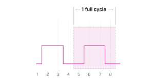
A pulse is a measure of the waveform from one identical point to the next
Detents are useful in providing feedback to the user by “clicking” into place as the shaft is rotated. Detents are specified as the number of clicks per 360-degree rotation. These prevent unwanted rotation and provide a “click” every time the shaft is rotated a certain number of degrees.
The push switch feature simply provides another user input signal. The encoder shaft can be pressed down to actuate a simple SPST switch. It is often used to select the function to be manipulated by turning the encoder knob.
Other encoder considerations
Rotary encoders utilise square waves with two channels that are offset 90 electrical degrees from each other. By detecting which channel is leading the other, direction can be monitored.
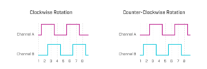
By detecting which signal is leading, the direction of rotation can be monitored
Most applications will use quadrature state changes to increase the counts per revolution. Increasing the counts per revolution increases the effective resolution of the encoder. In this case, one cycle is a transition from low to high back to low on both channels.

Microcontrollers use different methods for counting:
- Pulses on one channel: 1 count per pulse
- Pulses on two channels: using both channels doubles the number of counts
- Quadrature state changes: 4 counts per cycle
Most panel mount encoders need to be connected to a microcontroller that can source current. The microcontroller provides a path to V+ and the encoder provides a path to ground creating a complete circuit. Another term commonly used for sinks is “open collector.” This means the collector of the output transistor is external to the unit.
Mechanical vs. optical encoder technology
Panel mount encoders utilise two main technologies for operation: mechanical and optical. Mechanical encoders are essentially a series of switches. The code wheel contains contacts spaced evenly along its outer edge. Another contact is stationary and mounted on the encoder chassis. As the code wheel turns it makes, then breaks, contact with the code wheel contacts, one at a time. This making and breaking of a circuit generates a voltage pulse.
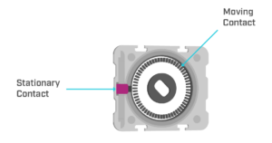
Basic working principle of a mechanical encoder
It is important to note that because mechanical encoders are essentially a series of mechanical switches, they require debounce circuitry and programming to ensure that the output can be used. In a perfect world, a switch is characterised by having two states, on and off. Unfortunately, in the real world, switches can hover or bounce between the two states, creating a distorted signal. Switch bounce can be incorrectly read as additional pulses. To prevent this debounce, circuitry is used to “square up” the output.

Debounce helps to provide a clean signal when switching between two states
Optical encoders are made up of three basic parts: a light source, a light detector, and a code wheel. The source shines light through slits in the code wheel and the detector senses this light. The code wheel has evenly spaced slits which transmit and alternately block the light source. Internal circuitry enables and disables an output depending on whether or not the light is being detected or blocked.
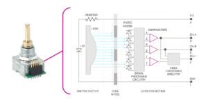
Basic working principle of an optical encoder
Mechanical encoders are less expensive and can handle a wider range of voltages. However, they require debounce circuitry to produce a clean signal and have a shorter life cycle. Optical encoders, on the other hand, are typically more expensive but have a higher life cycle and provide a cleaner output signal that does not require debounce circuitry. Additionally, for precision applications, optical encoders can provide higher resolutions.
Conclusion
Panel mount encoders will continue to find use in a wide range of user interface applications. Understanding the encoder technologies available, key specifications, and design considerations will be crucial for proper device selection. CUI Devices offers a range of mechanical and optical panel mount encoders for virtually any design need.
Learn more about this and many more topics on the CUI Insights page.