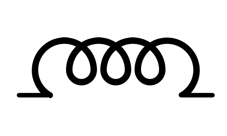
Inductance is an ideal electric circuit component which is close to the inductor in its features and components – collecting the energy of magnetic field. The letter L is used as the electronic circuit component mark, and its value at the same time. Inductance of the circuit is derivative of the self-induction of the circuit part to the current:
Magnetic flux here is a sum of magnetic flow times the quantity of inductance turns. This was the simplest case of magnetic field in the ideal inductor. The measurement unit for inductance is Henry (Hn), self-inductance is measured with Weber (Wb).
Electro-magnetic inductance, Faradey’s Law, says that change of magnetic field provokes electro-motive force of self-inductance, and is shown as the following:
Lenz Law describes the principle of electro-magnetic inertia. Electro-motive force of self-inductance is opposite to the magnetic flux, that’s why there is a minus symbol in the formula.
If inductance L is not related to current I, then we have the following equation:
and
uL is inductance voltage.
Instantaneous power on the inductance is
This quantity is closely related to increasing and decreasing of the magnetic field on the inductance.
If the part of magnet flow of the inductor is related to another inductor as well, then these two inductors also have characteristic mutual inductance M. Mutual inductance is the ratio of magnetic flux of the inductor 1 to the current that goes through inductor 2:
Inductor 1 and inductor 2 have their electromotive force related to the mutual inductance:
We take into account that M is not related to current I, because all components are linear. Mutual inductance units are shown in Henry (Hn). And this parameter M is not a feature of some selected component, but in relation to the couple of inductors.


