In today’s fast-paced ever-growing world, technology has paved the way for innovation and learning across the globe. From urban metropolitans to remote rural settlements, we are all more connected than ever – bridging the gaps between all boundaries, sharing knowledge, and learning in each step of the way. With our daily lives surrounded by gadgets and gizmos we are left to wonder; how do they work?
Written by Ibrahim Irfan
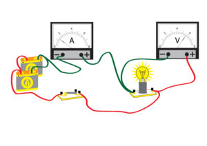
Objective : To understand the current-voltage relationship in non-linear circuit components.
It’s December and the streets are beginning to show colours of red and green. The first snow has fallen and everyone is starting to prepare for the Christmas holidays. Most of us have experienced the season of joy and giving, eagerly waiting for Santa to lay down our presents under the beautifully decorated Christmas trees.
As preparations are underway, a variety of lights chained with wire are hung around the Christmas tree, around down and across the world. Some say it brings in the warmth of Christmas. Electricity is an important factor that supplies the energy to power these types of lights, each working in an oddly eye-catching way.
Types of resistances
In the previous article, a gross overview of resistance is given. To recap:
- Resistance – The opposition to the flow of current within a component.
- Current – Rate of flow of charge.
- Voltage – energy transferred per coulomb (or unit) of charge.
- Energy cannot be created or destroyed but transferred from one form to another.
- Resistance can be calculated by finding the value of voltage over current.
In a typical circuit, charge carriers have a smooth journey from the positive to the negative terminal, flowing down the concentration of the charge gradient. The presence of resistance creates a bottle-necking scenario which restricts the number of charge carriers that can flow through a section of the circuit at a time. In a real-life circuit, the transmission wire contains large positively charged protons and is surrounded by insulation, both of which contribute to a negligible level of resistance.
⚠Do not attempt to connect directly connect the positive terminal of a power supply to its negative terminal. The negligible resistance created travels over a value of voltage which is limited by the supply. However, this means the current changes to accommodate for the minute value of resistance, creating an almost infinite current. This is called a short circuit and can be very dangerous to health. ⚠
The use of circuit elements, therefore, creates a voltage gradient that not only deems the circuit safer to use, but more useful. Every component in a circuit can be said to have a resistance to the flow of charge carriers, which ultimately creates a potential difference.
As you go further with your learning, it is quickly prevalent that not all types of resistances are the same. For example, the current and brightness of a filament lamp start to peak after a certain voltage while a typical 100-Ohm resistor shows a proportional change between current and voltage.
This principle was acknowledged and since resistors can be classified into two distinct groups:
- Linear resistors
- Non-linear resistors
These resistors can be further classified into many common types of resistors according to their characteristics. It is best to visualise each resistor using a I-V (current-voltage) graph.
Linear resistors
Resistors that demonstrate a direct proportion between current and corresponding voltage response independent of the negative and positive direction of flow are commonly classified under Linear Resistors. These are Ohm’s Law following resistors over a certain temperature.
Such resistors can be found in further two forms:
- Fixed Resistor
- Variable Resistor
The values of this family of resistors can be plotted on an I-V graph as follows:
It can be noted that the value of resistance can be extrapolated along the gradient, which is linear, hence the name. These are the most common type of resistors and can be found in just about everything you can imagine, whether your television, mobile phone, or even an array of light bulbs to light your Christmas decorations!
Above is a variety of variable resistors, each able to change the resistance in different ways but giving the same ultimate result.
Non-linear resistors
Some components, however, do not diligently follow Ohm’s Law across a circuit. Instead, these components exhibit their unique characteristics which can be implemented in creative ways through electronics.
Components which do not follow a direct proportion between current and potential difference across them are known as Non-linear resistors. There are a few common component characteristics that are useful to know:
Filament lamp
Filament Lamps are commonly represented as a typical light bulb in basic circuit diagrams and are assumed to have no resistance. In reality, it is quite different. It has an I-V graph of the following:
As you can see, the element initially has a linear relationship between current and voltage, similar to a linear resistor.
However, as the potential difference increases, the proportional increase in current begins to decrease and the graph begins to plateau. This phenomenon is due to the physical constraints of the filament lamp. As the voltage increases, the tungsten core behinds to produce significant levels of thermal energy which is released in the form of heat loss. The temperature of the filament lamp increases which ultimately limits the current that can flow through the bulb.
Above is a typical filament bulb and its circuit symbol. Due to the large levels of energy loss, the use of lightbulbs has seen a gradual decline, being overtaken by LEDs.
Diodes
Diodes are extremely common and useful tools in electronics. These elements only allow a significant current flow in one direction (the forward direction) and have very high resistance in the other direction. An I-V graph of diodes is as follows:
Such a peculiar characteristic of a device is due to the component being made from semiconductor materials. The special property of diode gives greater flexibility to innovators and engineers to design their circuits and make them more versatile.
Two of the most common types of diodes are Light Emitting Diodes (LEDs) and photodiodes (Light Dependent Resistors or LDRs). Your Christmas tree is most likely to be lit with LED lights!
Thermistors
Thermistors are another fascinating electronic device. This device is a type of variable resistor that changes resistance depending on the temperature of its surroundings. As the temperature of the thermistor increases, the resistance exponentially decreases and can pass a larger level number of charge carriers to flow through it per unit of time, hence increasing the current in that circuit.
From simple Arduino temperature sensors to larger-scale use of thermistors in air conditioning systems and greenhouses, this type of semiconductor has multiple benefits and can be used in a variety of work situations. A thermistor is possibly present as a part of your room’s heating system giving you a comfortable time at home!
Above is a typical LED diagram. It is important to note the two arrows pointing outwards which signifies that it’s a light emitting component, type diode. A photodiode has a very similar circuit diagram, the difference being the arrows pointing towards the diode.
Now that you have acquired or refreshed your memory on the type of resistors, try to spot creative uses of resistors and comment them down below to let us know of your incredible findings.