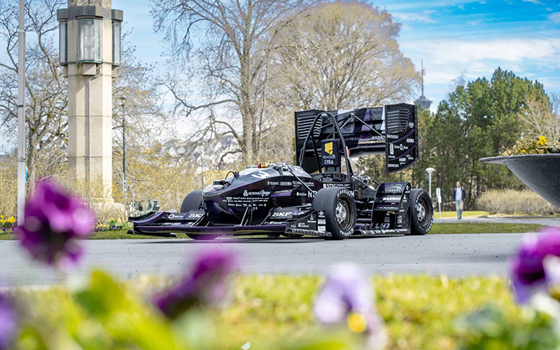
Revolve NTNU is a student organisation at the Norwegian University of Science and Technology in Trondheim that each year designs and manufactures a race car to compete in Formula Student competitions around Europe.
The team consists of students from approximately 16 fields of study who all need to cooperate to maximise performance in the coming race season. With a member retention rate of only 35%, many in the team face a quick and steep learning curve in understanding their system, how it performs, and what changes can be made to optimise it.
Our embedded electronics group is responsible for both hardware and software, giving members a thorough understanding of the entire system. As most of the time is spent developing the hardware, the team needs a way to quickly grasp the software architecture before they can start working on their hardware.
This year, a goal was to improve the high voltage measurement system by moving it to a dedicated printed circuit board (PCB) with a new digital sensor IC that offered enhanced failure detection capabilities over the previous analog hall effect sensor.
The chosen IC supported multiple inputs, enabling the integration of high voltage measurements via a megaohm-range voltage divider. While this functionality could have remained on the main microcontroller PCB, isolating it on a separate smaller board streamlined integration with the mechanical structure and wiring harness. This isolation approach also simplified compliance with relevant safety standards. By decoupling the high voltage measurement subsystem, the team enhanced robustness, simplified integration, and upheld critical isolation requirements.
This protocol has been used before, therefore the data on how it behaves is easily accessible. Detailed information provided by Percepio Tracealyzer, in combination with good naming practices, made it possible to calculate the total delay and possible sampling frequency on the new PCB.
Mutexes are used throughout the code to ensure that there are no conflicts with shared resources. By measuring how long each mutex is taken, we can estimate how much time a certain operation or calculation takes. Previous data show that receiving a value, packaging the CAN bus frame, and sending the data over the physical peripheral takes 7 µs. Furthermore, calculations that need to be done before the data is sent take 10 µs and, assuming that the new communication bus will behave like on other systems, another 5 µs is required to transfer the data to the MCU. The external sigma-delta ADC with modulator has a maximum conversion time of 821 µs. Adding all these delays tells us that there is an 843 µs delay from the sample being requested until the data is available on the CAN bus. The possible maximum sampling rate will thus be 1218 Hz.
As 500 Hz is the target sampling rate for this system and the delay is within acceptable bounds, this was enough empirical data to greenlight the new concept.
Later, when all hardware was developed and the new drivers were written, we began to look for places to optimise the code. With a new developer pretty much every year, and a repository with many submodules and over 60,000 lines of code, finding small software optimisation opportunities was very difficult.
Again, Tracealyzer was a big help. The picture below shows that the DC-DC task takes up significantly more time than any other task in the system. This task gets 8 32-bit float values but uses twice as much processor time as another task that grabs 144 such values and then also does some conversion and calculation before sending them to the CAN bus.
This is an easy way to locate spots where we may have a problem, such as a driver that is unoptimised or stuck busy waiting for data transfer. Finding bugs like these proves to be very difficult without the visualisation tools available through Tracealyzer.


