

This post answers the question “What are CAN interfaces?”. It’s a two-wire, half-duplex, and high-speed network system. With respect to functionality and reliability, the CAN Interface is quite superior to conventional serial technologies like RS232. There are great usages of CAN Interfaces in the fields of automotive and commercial vehicle industries, medical technology, machine-building industry, as well as aerospace.
What is CAN Interface?
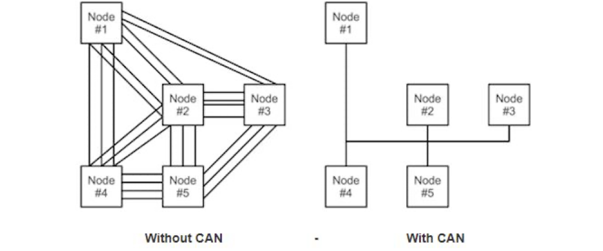
CAN Interface which stands for Control Area Network is a standard designed to allow microcontrollers and other devices to communicate with each other without a host computer. It’s a serial communication protocol that helps to interchange data between electronic control units on automobiles. It facilitates the sharing of a great quantity of information between nodes and control units conjoined to the system and that’s why it reduces both the number of sensors required as well as the number of wires in the electrical installation. So, using the CAN interface, the ECUs(separate electronic control units inside a vehicle can easily communicate with simply a single pair of wires.
Who is the CAN interface designed for?
Basically, the CAN interface reduces the wiring required between a control system and Input/Output( I/O )devices. So, who wants to read vehicles alternatively drivetrain sensor data from their ECU or various CAN devices without the requirement for additional sensors, the CAN interface is designed for them.
There are several common parameters like coolant temperature, engine speed, throttle position, etc, that are found from the engine control unit (ECU). So, if you use the CAN interface, you don’t have to use additional sensors.
CAN Interface Message/Frames
There are two different CAN interface frames or message formats that a CAN interface network can be configured to work with them. One is the standard or base frame (CAN 2.0 A) and the other frame is the extended frame (CAN 2.0 B).
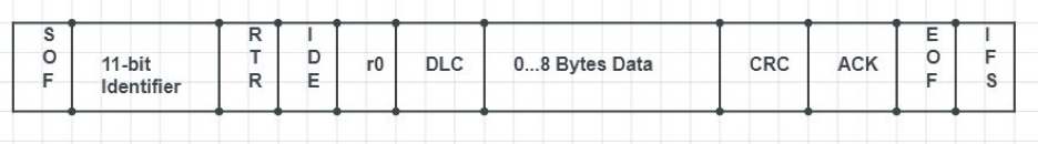
Standard CAN Interface
The standard CAN interface message frame supports a length of 11 bits for the identifier. The standard CAN interface message frame supports a length of 11 bits for the identifier. These are the following in the figure.
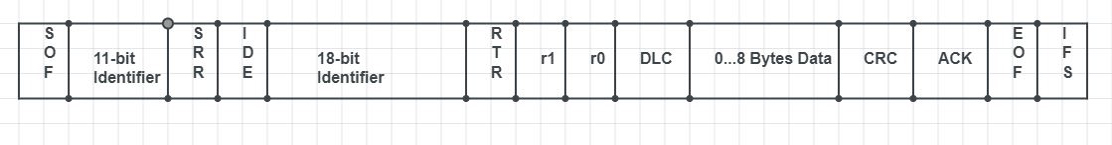
Extended CAN Interface
The Extended CAN Interface frame consists of 29 bits of the identifier, (11-bit identifier, 18-bit extension). These are the following below.
Types of CAN Interface Message/Frame
There are 4 types of CAN interface frames. They are the following:
- Data frame: The data frame handles the data, the identifier, the cyclic redundancy check, the data length code, and the acknowledgment of bits. In the data frame, both the transmitter and receiver acknowledge a successful transmission on the condition that the recessive acknowledge bit is overwritten at the receiving end by a dominant bit.
- Remote frame: It looks like the data frame but it contains no data. The remote frame is used to request the transmission of a specific identifier.
- Overload frame: It’s a frame that provides a time buffer between data or remote frames so that the node could catch up.
- Error frame: It detects the error and retransmits the message.
Conclusion
In fact, the CAN interface was first made for automotive use. But, although it’s a very usual and important application in vehicle electronic networking, there are vast uses in industries, railway applications as well as medical sectors. The use of CAN interfaces is increasing day by day because of its low cost, error capabilities, lightweight network, broadcast communication, and priority of every message.