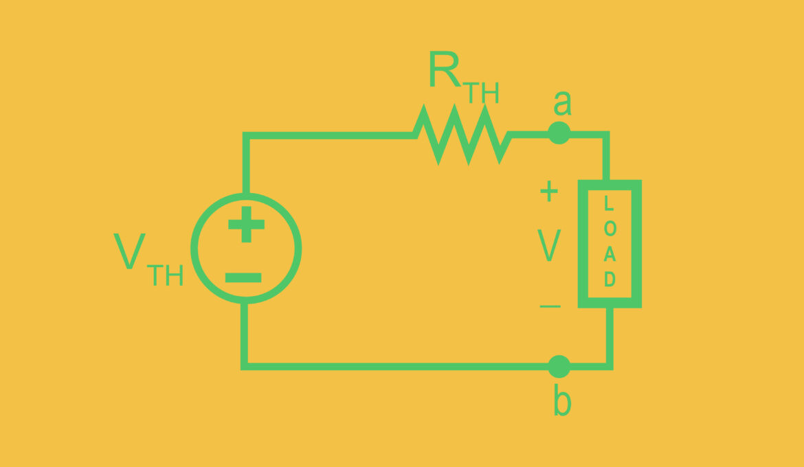
Thevenin’s Theorem stands as a pivotal concept in electrical engineering, offering a simplified method for analysing complex circuits. This theorem, named after the French telegraph engineer Léon Charles Thévenin, proposes a technique to reduce any linear, bilateral circuit to an equivalent circuit consisting of a single voltage source, series resistance, and load. By transforming intricate networks into a more manageable form, Thevenin’s Theorem facilitates easier analysis, particularly beneficial for understanding circuit behaviour and for the design and troubleshooting of electrical systems.
Understanding Thevenin’s Theorem
At its core, Thevenin’s Theorem asserts that any complex linear circuit with resistors and sources (voltage or current) can be simplified to a single voltage source (V<sub>TH</sub>) and a series resistance (R<sub>TH</sub>) connected to a load. This theorem applies to AC circuits as well, where impedance takes the place of resistance.
Practical applications of Thevenin’s Theorem
Simplifying circuit analysis
Thevenin’s Theorem is instrumental in reducing the complexity of electrical circuits. By simplifying the network to a basic two-element circuit, engineers can easily determine the current flowing through and the voltage across the load. This simplification is particularly useful in systems with multiple components and interconnections, where direct analysis would be cumbersome.
Design and testing
In the design phase of electronic devices, Thevenin’s Theorem aids in the modular design approach. Engineers can analyse individual components of a larger system in isolation before integrating them into the whole, ensuring compatibility and performance standards are met. This theorem also proves invaluable in testing circuits by enabling the isolation of certain sections for detailed examination.
Educational tool
For students and newcomers to electrical engineering, Thevenin’s Theorem serves as a fundamental learning tool. It provides a clear, step-by-step methodology for circuit analysis, reinforcing the understanding of basic electrical principles and the interplay between circuit elements.
Applying the theory
- Identify the portion of the circuit to be analysed and remove the load resistor if one is present.
- Calculate the open-circuit voltage (V<sub>OC</sub>) across the terminals where the load was connected.
- Determine the Thevenin resistance (R<sub>TH</sub>) by deactivating all independent sources within the circuit (replace voltage sources with short circuits and current sources with open circuits) and calculating the resistance seen from the open terminals.
- Construct the Thevenin equivalent circuit using the values obtained for V<sub>TH</sub> and R<sub>TH</sub>, with the load reconnected to the terminals.
Applications in the real world
The practicality of Thevenin’s Theorem extends beyond the theoretical to real-world applications such as power distribution, telecommunications, and the design of electronic devices. For instance, in power systems, it can be used to approximate the voltage across and the current through a house when connected to the electrical grid, taking into account the resistance of the wires and the potential drop.
Concluding thoughts
Thevenin’s Theorem is a testament to the elegance and utility of electrical engineering principles. By offering a systematic approach to circuit simplification, it not only enhances our understanding of circuit behaviour but also streamlines the design, analysis, and troubleshooting processes. As we continue to advance in the development of complex electronic systems, the relevance and application of Thevenin’s Theorem remain as significant as ever, underlining its timeless value in the field of electrical engineering.


