Series RLC resonant circuit is used to model a resonator at frequencies close to resonance. Resonator is a system, demonstrating resonance behaviour. Resonance in a circuit occurs when power stored in the inductor is equal to power stored in capacitor.
Example of this circuit is shown below.
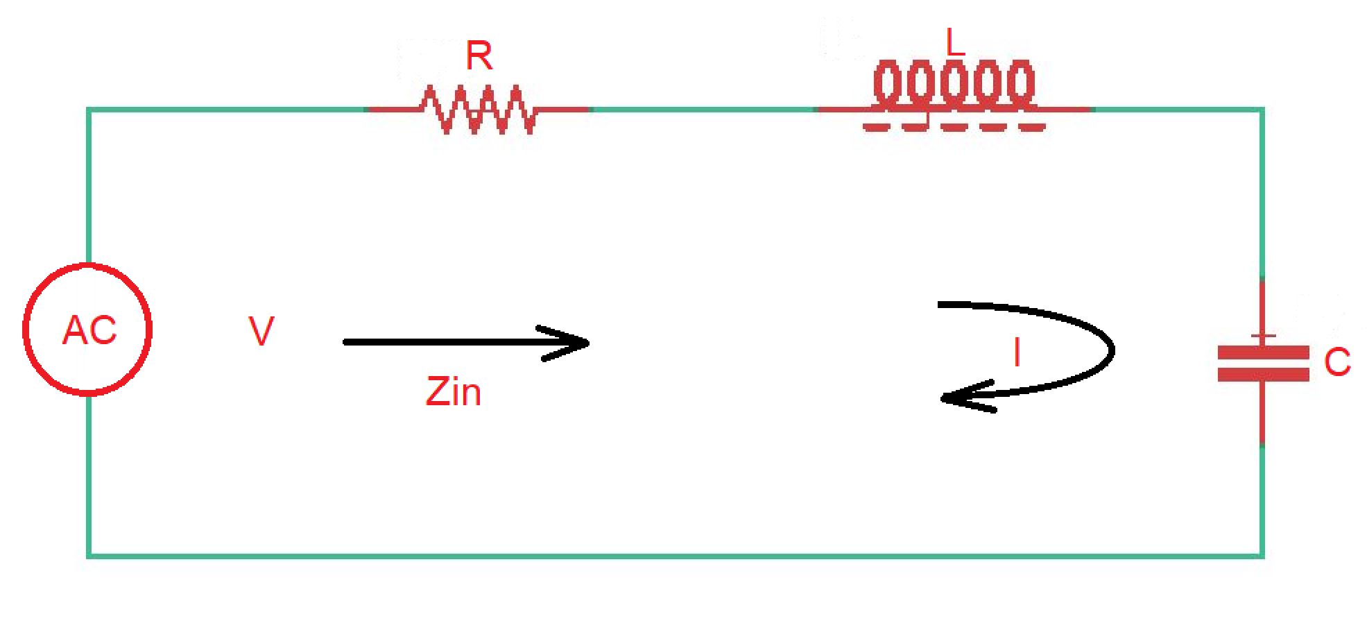
Here input impedance and power delivered to resonator is .
Power dissipated on the resistor is . Magnetic energy stored at the inductor is . Electric energy stored at the capacitor is .
So total power for this circuit is . At the same time . Here we can get the input impedance as .
The condition of resonance is equality of energies stored at capacitor and inductor. So , and input impedance is equal to resistance . And because .
Resonant circuit is characterised with the quality factor , which is always proportional to the energy stored in a circuit and energy lost in a circuit.
The reasons of losses in a circuit can be :
- conduction losses;
- dielectric losses;
- radiation losses;
- external circuit losses.
If resonator does not have external circuit, it is called unloaded, and it’s quality factor is . In the other case resonator circuit is loaded and quality factor is .
In case of unloaded resonant circuit easy to show that .
Let’s consider input impedance in the area of resonance , where : , where .
Mathematically we can show that , so .