In this introduction to power electronics and power circuits we will discuss energy devices and energy control. All the processes in our daily lives are connected to electricity and energy conversion. So energy, its savings and conversion is important in every human activity. It is challenging to design circuits in terms of proper energy saving and conversion.
Power electronics and power circuits is a discipline intended to control electrical energy flow in a circuit. In the study of electrical engineering power electronics and power circuits is placed on the same level as radio frequency, digital and analogue electronics. There are also many applications for power electronics and power circuits, like phones, cars, wearable electronics, industrial electronics and other applications.
All electric circuits manage the electrical flow between electric load and the source. For example, a general system of electric power conversion can be seen in Figure 1. The function of the power converter is to control the energy flow. Building such a scheme we must take into consideration the losses in this system. The energy conversion also affects the reliability of a system – even if the source is very reliable, failure of the converter provokes problems on the load.

Classification of power electronics and power circuits
Power electronic devices are divided into five groups: power diodes, thyristors, power bipolar junction transistors (power BJTs), insulated-gate bipolar transistors (IGBTs), and static induction transistors.
Power diodes, shown in Figure 2, are similar to classical semiconductor diodes. The only difference is that they can carry significantly bigger currents. To refresh the knowledge about the semiconductor diodes, they can perform under two regimes – forward-biased and reversed-biased. If the potential to the anode is higher than the cathode potential, then the diode works in the forward-biased regime. In the reversed-biased regime, the current flowing through the forward-biased diode is called forward current. Current through the reversed-biased diode does not flow.
Power diodes are subdivided into three categories: general purpose, high speed and Schottky. The general purpose diodes operate with current and voltages of 3,000V and 3,500A, high-speed – 3,000V and 1,000A. A Schottky diode is characterised by very short switching times, but the voltage and current are not as big as it is for other power diodes: 100V and 300A. Forward-biased voltage for power diodes is minor compared to work voltages. The defining characteristics of a power diode is their power rating.

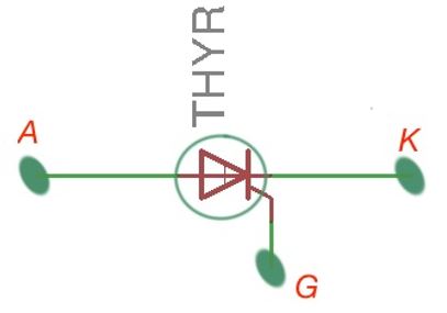
A thyristor, depicted in Figure 3, are similar to semiconductor diodes, but have an additional gate that is responsible for turning on the conduction at the thyristor – when the small current is injected into the thyristor and the anode voltage is greater than the cathode voltage. The conduction stops when thyristor is reversed-biased.
The voltage and current ratings for a thyristor are 3,500A and 6,000V. The most important parameter for a thyristor is switching-off time – time that is needed for a device to zero the current after it is reverse biased. The fastest turn off ratings can be achieved only for thyristors with small ratings.
Thyrisors are subdivided into the following groups: force-commutated thyristors, line-commutated thyristors, turn off thyristors (GTOs), reverse-conducting thyristors (RCTs), Static Induction thyristors (SITs), gate-assisted turn-off thyristors (GATTs), Light Activated Silicon Controlled Rectifiers (LASCRs), and MOS controlled thyristors.
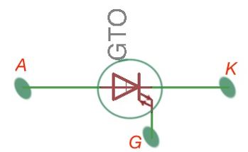
The gate turn-off thyristor (GTO), is depicted in Figure 4, and can be turned on by applying a positive pulse to the gate, and can be turned off by applying a negative pulse to the gate. These thyristors do not require the separate commutation circuits to manage them.
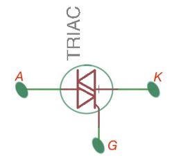
The triac, depicted in Figure 5, is a device that features back-to-back connected thyristors, that allow the control of current in both directions.
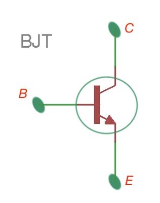
Power BJT, depicted in Figure 6, reaches the ratings of 1,200A and 400V. It is similar in functionally to an ordinary BJT. It is usually used in converter applications with frequencies of 10kHz.
Power MOSFETs
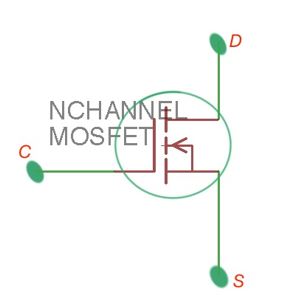
Power MOSFETs, depicted in Figure 7, operate at higher frequencies, 10-50kHz, but its ratings are limited by 1,000V and 50A.
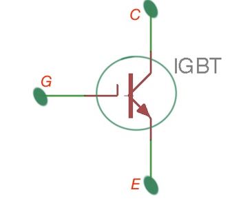
Insulated-gate bipolar transistors (IGBT), are depicted in Figure 8. They are voltage controlled, and have ratings between BJTs and MOSFETs.
All the devices above are parts of power circuits. Power circuits can also be divided as the following:
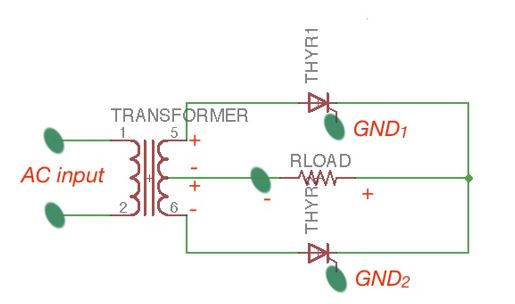
Voltage regulators regulate a DC voltage at a certain rate; power switches, operate like ordinary electronic switches, and turn AC and DC supplies on and off; transistor power amplifiers amplify large signal voltages and currents – it’s also important to realise that they feature power limitation and signal distortion. Diode rectifiers convert AC signal into DC signal, as described in a the ‘Semiconductor devices’ section (and can operate with a multi-phase signal). AC-DC converters have a functionally similar to a diode rectifier, and also has the function of a thyristor to control the turning off time. AC-DC converter is depicted in Figure 9. It is also called a controlled rectifier.
These converters are based on rectifiers, and as mentioned below, there are two types of full-wave single-phase rectifiers: full-wave rectifiers with centre-tapped transformer and bridge rectifiers. The full-wave rectifier with a centre-tapped transformer is shown in Figure 9.
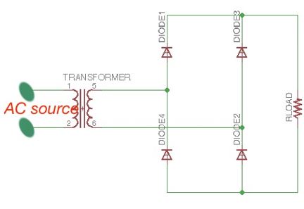
Each half of a transformer is connected to the half-wave rectifier, and their outputs are combined to perform a full-wave rectifier. The bridge rectifier is presented in Figure 10. The difference is that a bridge rectifier does not need a centred transformer, and the PIV of the diodes is many times lower in this case than for a full-wave single-phase rectifier.
AC-AC converters / DC-DC converters
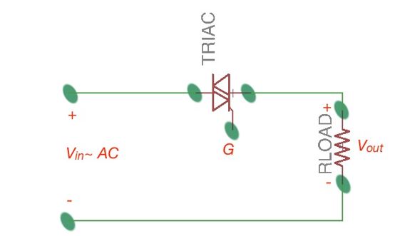
AC-AC converters convert fixed AC voltage to variable AC signal, and can operate with single or multi-phases. It is also called an AC voltage rectifier. It also performs the triac functions, and can be bideractionally controlled.
The resulting AC signal is changed, even if the frequency is the same. It is depicted in Figure 11. The AC-AC converters are used for getting the power signal from one signal and transferring it to another system with another frequency, magnitude or phase. The AC-AC converters that are characterised by transferring energy with constant frequency, are called AC voltage regulators.
The voltage control may happen in two ways: by phase control using commutation with triacs or rectifiers (SCR), or on/off control, with commutation provided by GTOs, IGBTs, power transistors, and other types of thyristors. The AC-AC converters that convert signal form with one frequency into the signal form with another frequency, are called cycloconverters. They are mostly commutated by silicon-control rectifiers. Cyclo converters and matrix converters provide independent control of magnitude and frequency of the output signal.
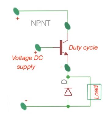
DC-DC converters converts DC signal to variable DC voltage. They are also called switching regulators or choppers. Figure 12 shows the DC-DC converter device. The variable output can be controlled by selecting the ‘on’ time for the converter, and results in the variable output duty-cycle. DC-DC converters are widely used in modern electric devices, as they allow the build of light, small, highly efficient and high quality power supplies.
The DC-DC converters convert DC input voltage into DC output voltage, reducing the AC ripple on the output signal, regulating DC output voltage in accordance to load, protects supplied systems from the EMI (electromagnetic interference) and provides isolation between the load and source.
DC-DC converters are divided into the hard-switching pulse with modulated converters (PWM), and resonant- and soft-switching converters. The advantages of PWM converters is that they are highly efficient, easy to understand, have low components, are easily controlled, and can perform high-conversion ratios.
The disadvantage is that they are characterised by the rectangular signal form, that causes the turn-on and –off losses. It limits PWM converters for utilisation only in the megahertz frequency range. PWM converters also can result in EMI. The most basic DC-DC typologies are: buck, boost, buck-boost, Cuk converters. The advantages, features and disadvantages of these converters will be explained further.
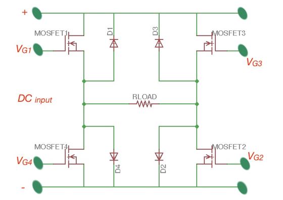
The DC–AC converters, or inverters, are used to convert DC signal to variable AC signals. Figure 13 depicts its structure. These converters are used in adjustable speed drivers (ASD), active fibres, uninterruptable power supplies (UPS), static var compensators, flexible AC transmission systems (FATS) and other applications that require an AC waveform. For these applications, wave magnitude, frequency and phase must be controllable. The most used topology for these applications are voltage-state inverters (VSI). Also this topolgy can be recognised as current-state inverters (CSI). All power electronic devices and circuits for various applications can be found at the website of Digi-Key supplier of electronic components