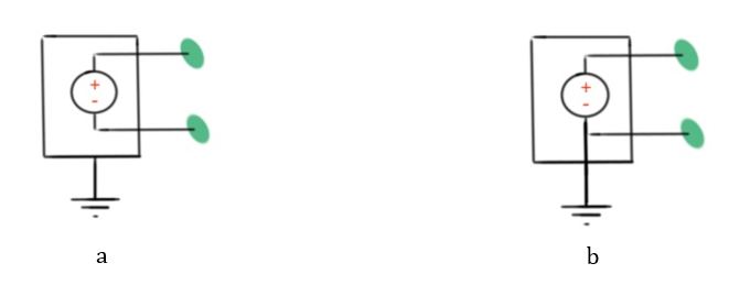
This post answers the question how to reduce noise in a circuit. During circuit design it is important to make a proper connection between different circuit elements to avoid effects like screening, noise and others. There are two types of signal sources – floating and grounded. A grounded signal source is one with stable ground reference. A floating signal is one where all the signal leads are not connected to the ground.
A measurement system can be ground-referenced and differential. For ground-referenced measurement systems, the signal is connected to the instrument case ground. In the differential system all the connections are connected to the ground, so it’s good to measure the potential difference between signal levels.
The problem of the grounded signal source is the appearance of ground loops in a system, which is current path created by the connection of two different voltage levels. Ground loops are a significant reason of undesired noises in a circuit. The usage of differential measurement systems can resolve the problem of ground loops.
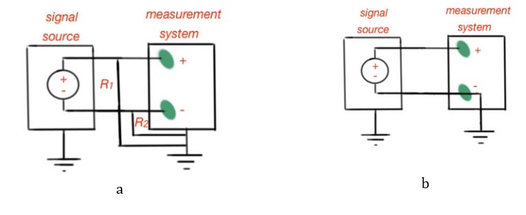
When a differential system is used the source and measurement system ground connections are not connected to each other. In case a floating source is connected to the differential system, it’s better to reference the source connections to the ground, using resistors. Types of floating signal source connections to the differential system are depicted in Figure 2.
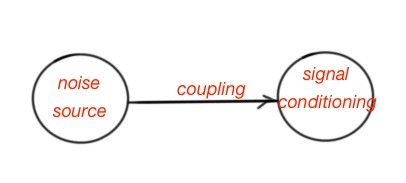
All the measurements have some noises, the undesirable signal interference. Noise measurement consist of a few steps, shown in Figure 3. The first one is the determination of noise source. Noise sources are present in every circuit, and can be in every circuit element.
The second step is noise coupling. Noise coupling mechanisms are conductive, capacitive, inductive and radiative. Conductive coupling occurs due to the noise conduction along the wires between the source and the circuit elements.
Capacitive coupling occurs in the following way. Let’s assume that we have a noise source with a noise conducting wire. If the noise conducting wire is too close to the circuit conductor, it can create the electric fied, forming a capacitor. And this capacitor can transfer different types of currents.
Inductive coupling may occur in the case of large currents, so the noise source will create a significant magnetic field that will tie the noise source with the measurement system.
The figure below shows the noise sources that may include switching, high voltage, high current circuits, and AC power systems. The coupling mechanisms are conductive, capacitive, inductive and radiative.
There are a few ways to reduce noise in a system – to make proper wiring, grounding of a system, shielding and the use of twisted-pair wire. The shield is usually achieved with foil or copper tape and prevents conductive, capacitive noises, ground loops, but not inductive noises. The inductive coupling can be eliminated or reduced using twisted-pair wire.
More educational tutorials can be also accessed via Reddit community r/ElectronicsEasy.