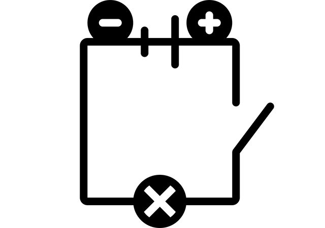
Four-terminal network is an abstract element of an electrical circuit, having four terminals – two-input and two-output. The four-terminal network is depicted below. If the four-terminals contain energy sources, it is called active for-terminal and marked with an letter. If not it is called passive four-terminal.
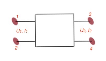
Here and are input voltage and current, and are output voltage and current. A four-terminal circuit is usually connected to load and source. The load and source parameters can be varied, but four-terminal characteristics do not vary. Parameters of passive four-terminals can be expressed with six equations, and every equation can be used in certain situations, depending on the four-terminal input data. These equations can be seen below:
- and
- and
- and
- and
- and
- and
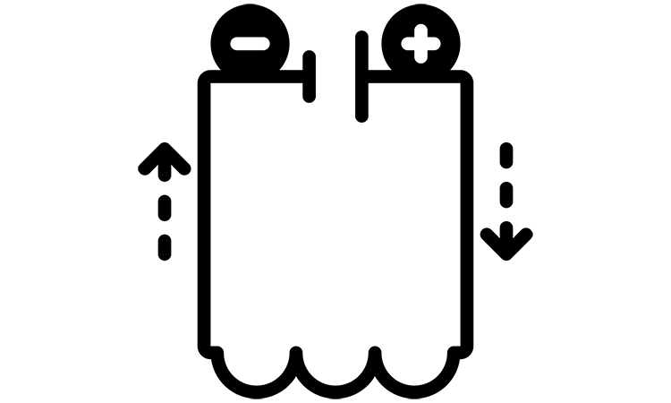
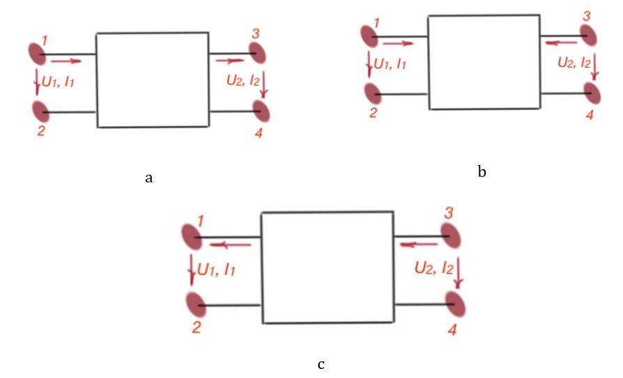
You can see that for the first equation, the positive direction of the current and voltage is depicted on the first picture; for equations 2, 3, 4 and 5 the positive direction of current and voltage is depicted on the the second picture; for the last equation, the positive direction of current and voltage is depicted on the third picture. The four-terminal is symmetrical; if we change the source and load, the currents and voltages in four-terminal circuits won’t change direction.
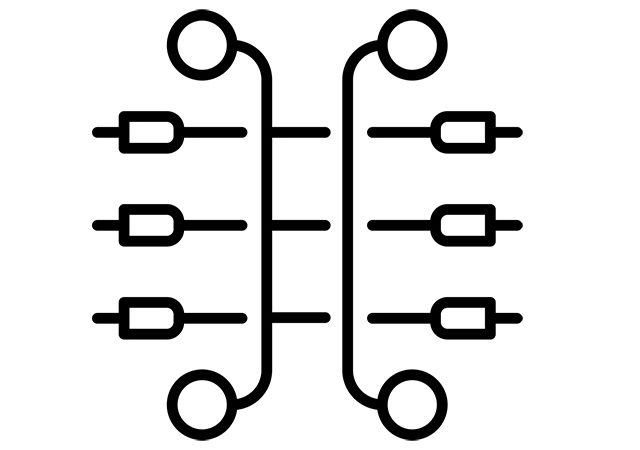
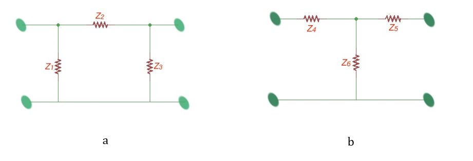
Passive four-terminals can also be replaced and simplified using the star or delta equivalent schemes, as shown on the figure below.
The transformations between equation coefficients for four-terminals can be given without intermediate conclusions.
Different four-terminal equations can be used depending on the situation. For example, for the synthesis theory, and equations are usually used. For transistors , and equations forms are good.
When the task is to find the input and output currents and voltages, we can use combinations of different forms of the equations. When four-terminals are connected, as shown in figure below labelled , its good to use -form of equations. When four-terminals are connected like in on the figure labelled , it’s good to use -form. When the four-terminals are connected like on the figure labelled , it’s good to use -form equations. When the four-terminals are connected like on the figure labelled , it’s good to use -form. When the four-terminals are connected like on the figure labelled – it’s good to use the first form of equations.
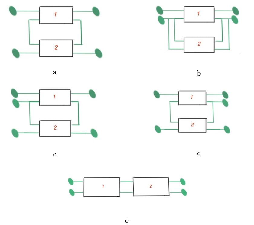
A four-terminal -matrix for the four-terminals depicted on the figure labelled is equal to the sum of these four-terminal matrices. Four-terminal -matrix for the four-terminals depicted on the figure labelled is equal to sum of these four-terminal matrices. We can make the same conclusions for the -matrix of the four-terminals on the figure labelled and -matrix for the four-terminals on the figure labelled .
When the four-terminals are cascade connected, it’s better to use -matrix, as it is equal to the product of these four-terminal matrices. This was the example of how to chose the correct form of matrix, and that depends on which is easier to use. In the case of figures labelled , it is important that the primary terminals should carry the same amount of current but in the opposite direction. The secondary terminals should also carry the same amount of current in the opposite direction.
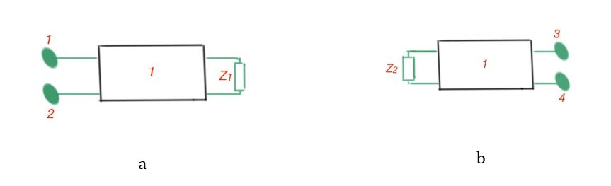
When the four-terminal circuit is not-symmetrical it is important to pay attention to the resistances , when the load is connected to the terminals 3-4, and when the load is connected to the terminals 1-2. To calculate these resistances we can also use the equations above.
The equations above also can help us to calculate attenuation or amplification of the four terminal circuit: (Bells), if the load is coordinated across the four-terminal circuit.