
This magnetic structure is very simple due to its consistency and is very wide spread in the application of measuring linear and angular velocity. The configuration of the sensor is depicted below.
Here the magnet with a coil wound around it forms a sensor. The steel disk rotates between the magnet poles. There is number of tabs on the disk, their cross-section is equal to the distance between the magnet poles. The tabs consist of ferromagnetic material. When the tabs are between the magnet poles, its reluctance changes.
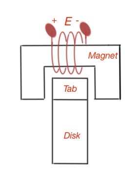
The idea of the sensor is that the EMF of the coil is E which is induced after the ferromagnetic tab passes between the magnet poles. When the tab goes between the magnetic poles, magnetic flux through the structure increases; as reluctance goes down, it reaches its maximum, when the tab is centred, and decreasing again as the tab is passes by.
The EMF here is , and the flux rate is dependent on the geometry of the tabs, poles and the speed of the disk rotation. Magnetic flux will change only when the disk is rotating. This sensor can be used in measuring the rotating speed of the electric machines and engines.
For example, for some machines a 60 tab wheel is used to convert the EMF directly to the units of revolution per minute. The output of the sensor should go to the comparator or Schmidt trigger. If the tabs are closely placed, the voltage waveform is nearly sinusoidal with the certain period related to the tabs.