This post answers the question “What is mesh and node analysis”. This two techniques are both used as basic analysis methods for circuits. When designing a complex electrical device there are a lot of factors that occur, like current leaks, heat flow, electromagnetic fields, behaviour of electrical materials etc.
In any case it’s always helpful to replace existing schemes by an equivalent network, where components are ideal. For instance, it’s easier to analyse an electric circuit when single sources, loads and passive elements are replaced with current and voltage sources and resistors. You will see below how to simplify analysis of complex circuits. It appears easier to calculate the scheme parameters counterposing a complex circuit and its equivalent analogue network. The nodal, mesh, loop and superposition methods will be discovered.
Nodal analysis
We discovered above the way of analysing simple circuits with two or three nodes. The nodal method will allow us to analyse circuits with four and more nodes in it. By the calculations above we found out the quantity on variable, voltages and equations will be , where n is quantity of nodes in a circuit.
In the nodal method we are finding the node voltages with the following steps:
- Select a reference node. Assign all the rest nodes voltages , with respect to reference node.
- Use Kirchhoff’s and Ohm’s Laws to each non-reference node and branch currents.
- Resolve the system of equations and obtain node voltages.
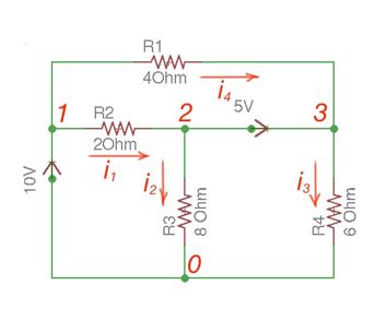
Let us discover the three node circuits in the Figure 1. There are two current sources and three resistors.
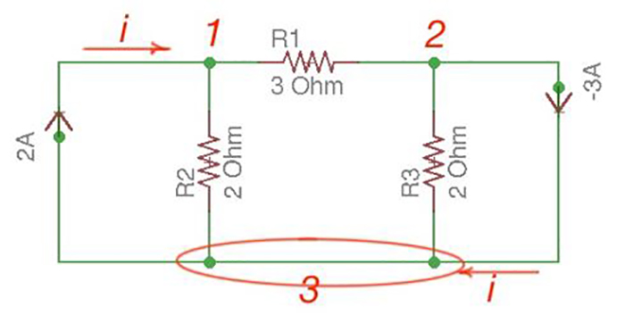
Let us consider a reference node – 3. In a real circuit a reference node is ground, it is assumed to have potential. A reference node can also be the one with the biggest quantity of connected branches like in our case.
By the Kirchhoff’s Law having the following current relation:
Let us represent currents like ratio of voltage and resistance by the Ohm’s Law:
;Or
And we achieve the following matrix equation, which can be resolved by the Cramer’s rule:
These types of matrices equations can be also resolved using MATLAB, Mathcad and other software.
Here a symmetric circuit was resolved. Let us consider a non-symmetric circuit – with a voltage source in a system.
Let us consider the scheme in the Figure 2.
There are two possibilities that exist:
- If the voltage source is between reference node and non-reference node, the non-reference voltage is considered equal to the voltage source.
- If the voltage source is between two non-reference nodes, these two nodes are considered to be generalised nodes. To determine its voltage Kirchhoff’s Laws must be applied.
Applying Kirchhoff’s Laws we achieve the following equations:
;By the Ohm’s Law:
These equations will help to determine node voltages.
The node method is a very generalised method of circuits analysis. This method can be applied to any circuit. However, it’s not the only one. Here below is the most commonly used method – Mesh method. It can also be applied to a lot of circuits and is considered as the most popular method.
Mesh analysis
Mesh analysis is applicable to the networks which are planar. Planar network is a network where branches are not passing over or under each other.
This method differs from the nodal method by using mesh currents instead of nodal voltages as circuit variables. This method is convenient as it allows us to reduce the number of equations that must be solved simultaneously. Nodal method uses Kirchhoff’s currents Law to consider nodal voltages, and Mesh method uses Kirchhoff’s voltages Law to consider mesh currents. Mesh is a loop, which does not contain any other loops.
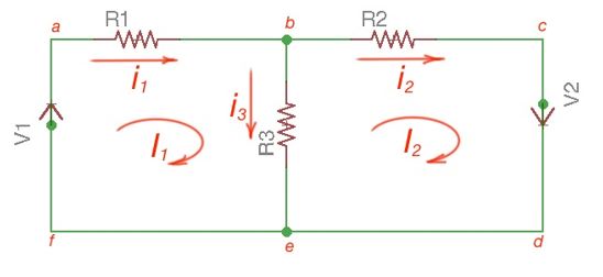
There are only two meshes in Figure 3 – abefa and bcdeb, abcdefa is not a mesh but a loop and Kirchhoff’s Laws work here. However, for Mesh method only meshes are in use.
Mesh analysis steps are the following:
- Assign mesh currents to all the meshes in a circuit.
- Apply Kirchhoff’s voltage Law to each mesh. Apply Ohm’s Law to determine voltages with mesh currents.
- To resolve simultaneously all the equations to consider mesh currents.
Note that directions of mesh currents are arbitrary, but it is better to suggest that they are all clock-wise (or vice versa), to avoid mistakes with signs in equations.
The following equations correspond to the Kirchhoff’s Voltage Laws for the meshes:
Using Cramer’s formula for resolving the matrix equations above we can find mesh currents, which allow us to consider currents in a circuit.
Current sources in a circuit will bring asymmetry in our equations and calculations. If there are current sources in the circuit, they have to be replaced by open circuits. The source currents should be considered as depending on the number of sources. Kirchhoff’s voltage Law can be applied for the closed circuits/meshes. Simultaneously resolving this equation, circuits and mesh currents will be resolved.
More educational and technical posts you can read at our Reddit community r/ElectronicsEasy.